In this third part of the STM32 ADC series, we explore how to use discontinuous mode to read multiple ADC channels efficiently. This mode allows precise control over channel sampling by breaking a regular conversion sequence into smaller steps, each triggered manually or by events.
In this guide, we shall cover the following:
- Introduction to discontinuous mode and usage to read multiple channels.
- Firmware setup.
- Firmware Development.
- Connection.
- Results.
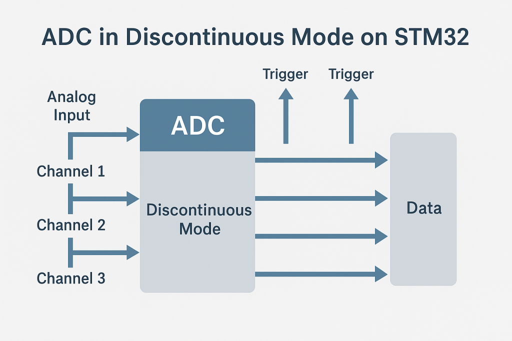
1. Introduction to Discontinuous Mode and Usage to Read Multiple Channels:
The Analog-to-Digital Converter (ADC) on STM32 microcontrollers is highly flexible and capable of reading multiple analog inputs through its multiplexer and configurable conversion sequence. One powerful yet often underutilized feature is Discontinuous Mode, which provides fine-grained control over how and when multiple ADC channels are converted. This mode is particularly useful in scenarios where sampling all channels in one burst is undesirable due to timing constraints, power concerns, or the need for more deterministic control over sampling order and timing.
What is Discontinuous Mode?
In Regular Group conversion, ADC channels can be arranged into a sequence of conversions (called ranks), and the ADC can convert them either in one go (scan mode) or in segments. Discontinuous Mode allows this conversion sequence to be split into smaller chunks—converting only one or a few channels per trigger event.
Here’s how it works:
- A conversion sequence is defined with multiple channels (e.g., Channel 0, 1, 2, 3).
- The Scan Mode must be enabled, and the number of conversions (ranks) specified.
- When Discontinuous Mode is enabled with
Ndiscontinuous conversions, each trigger (software or external) will start onlyNconversions out of the full sequence. - The next
Nconversions will occur with the next trigger, continuing until the full sequence is completed.
If N = 1, then one channel from the sequence is converted per trigger.
Why Use Discontinuous Mode?
Using Discontinuous Mode has several advantages:
- Precise Sampling Control: It allows sampling individual channels at distinct time intervals instead of sampling all at once. This can help align ADC sampling with real-world events or sensor timings.
- Lower Instantaneous Power Draw: Converting one or two channels at a time reduces peak current demand from the analog front-end, which is useful in power-sensitive designs.
- Efficient Resource Management: Discontinuous mode enables spreading out ADC conversions to avoid CPU or DMA bottlenecks when many peripherals are active simultaneously.
- Ideal for Multiplexed Inputs: If analog inputs are shared via external analog switches or multiplexers, Discontinuous Mode allows switching the input between triggers without racing against the ADC sampling window.
- Better Scheduling in RTOS: In FreeRTOS or similar environments, it integrates well into periodic tasks by converting only part of the sequence at a time per timer-based or task-based trigger.
Practical Use Case: Reading Multiple ADC Channels
Suppose you want to read 3 analog sensors (e.g., temperature, battery voltage, and potentiometer). Instead of sampling all three in a single ADC conversion trigger (which could be power-hungry or conflict with other tasks), you can:
- Enable Scan Mode and define the sequence with 3 ranks: Channel 0, 1, and 2.
- Enable Discontinuous Mode with
Discontinuous Rank Count = 1. - Trigger the ADC (via software or timer) every few milliseconds.
Each trigger will sequentially convert one channel in the sequence:
- First trigger: Channel 0
- Second trigger: Channel 1
- Third trigger: Channel 2
- Fourth trigger: Channel 0 again, and so on…
This behavior gives the system more breathing room between conversions, provides scheduling flexibility, and reduces overall power usage while maintaining synchronized acquisition across multiple channels.
Disadvantages of Using Polling Mode with Discontinuous ADC Mode
- Increased CPU Idle Time
Since polling requires the CPU to continuously check the End of Conversion (EOC) flag, it leads to wasted processing time—especially when waiting for each individual channel to convert in a discontinuous sequence. - Low Efficiency for Multi-Channel Systems
In discontinuous mode, only a subset (often just one) of the channels is converted per trigger. If you’re using polling, the CPU must repeatedly handle multiple software triggers and corresponding wait loops, making the whole acquisition process inefficient. - High Power Consumption
Because the CPU remains active during each polling cycle, it prevents the microcontroller from entering low-power sleep modes between conversions, which is particularly problematic in energy-sensitive applications. - Complex Timing Management
When manually triggering each conversion step and waiting for completion, precise timing between channels becomes harder to manage. This could lead to jitter or inconsistent sampling intervals, especially without the help of timers or interrupts. - Poor Responsiveness and System Scalability
Polling ties up the CPU, reducing its availability for other tasks like communication, real-time control, or UI updates. As more channels or peripherals are added to the system, the polling overhead scales poorly. - Risk of Missing Events or Data
If the CPU is stuck waiting for ADC completion and a higher-priority event (like a UART interrupt or real-time input) occurs, that event could be delayed or missed, harming system responsiveness. - Cumbersome Software Design
The control flow for polling each discontinuous step and channel requires more manual logic and careful sequencing, which complicates your firmware and makes debugging harder.
2. Firmware Setup:
From the setup of the previous guide from here.
Open.ioc file and STM32CubeMX window shall appear.
From left side menu, Analog and select ADC1 as following:
Enable IN1, IN2 and IN4 as single ended input (Not all STM32 has this feature).
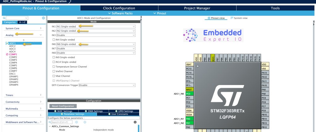
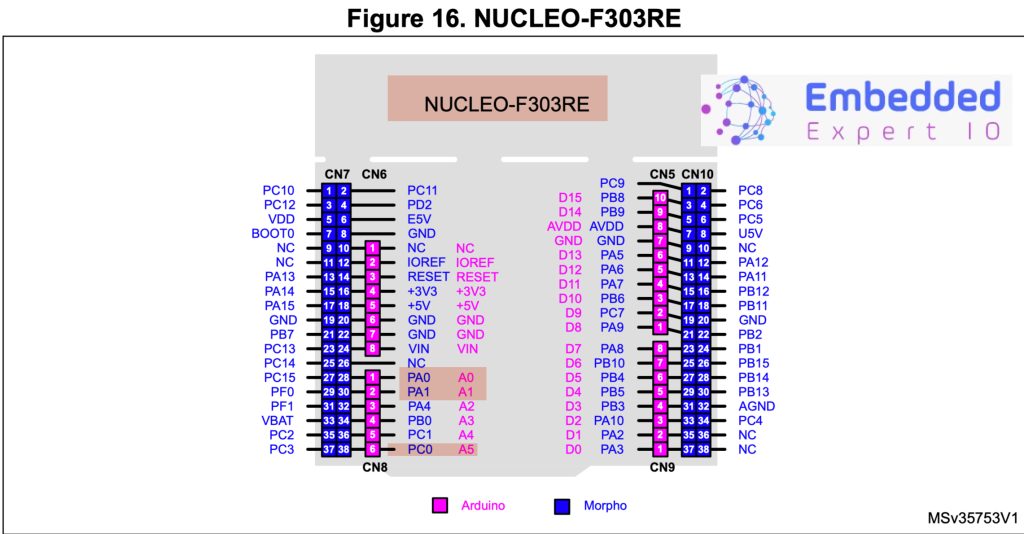
This will translate to A0, A1 and A5 analog pins of Arduino in STM32F303RE Nucleo-64:
Next, we shall configure the ADC as following:
- First, set Number of Conversion to 3, this will enable Scan Conversion Mode
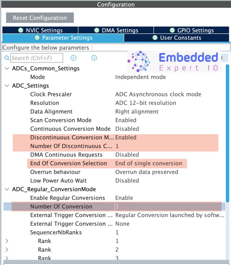
Next, set the rand of the channels as following:
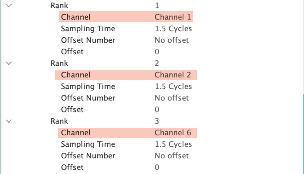
By setting the rank as shown, the conversion sequence shall be like this:
- Channel 1.
- Channel 2.
- Channel 6.
Thats all for the Firmware setup.
Save the project this will generate the project.
3. Firmware Development:
After the code has been generated, main.c shall be generated.
In main.c in user code begin PV (Private Variable), declare an array to hold the adc data of the three channels as following:
uint16_t adcValue[3];
Next, in user code begin 0, declare the following channel:
void adc_read_multichannel(uint16_t adc_buff[], uint8_t len)
{

	for (int i=0;i<len;i++)
	{
		HAL_ADC_Start(&hadc1);
		HAL_ADC_PollForConversion(&hadc1, 100);
		adc_buff[i]=HAL_ADC_GetValue(&hadc1);
	}
	HAL_ADC_Stop(&hadc1);

}
The function adc_read_multichannel shall read multiple channels in polling and takes the following parameters:
- Array to hold the measured ADC channels.
- Number of channels.
With the function, the sequence to read multiple channels as following:
- Start the ADC.
- Wait for the conversion to complete.
- Get the value.
- Repeat for the rest of the channels.
- Stop the adc after all channels have been converted.
In user code begin 3, call the function each 300 milliseconds as following:
	  adc_read_multichannel(adcValue,3);
	  HAL_Delay(300);
Thats all for the firmware.
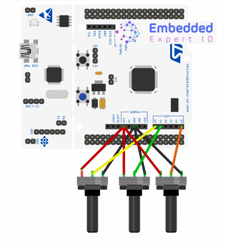
4. Connection:
The connection is as follows:
5. Results:
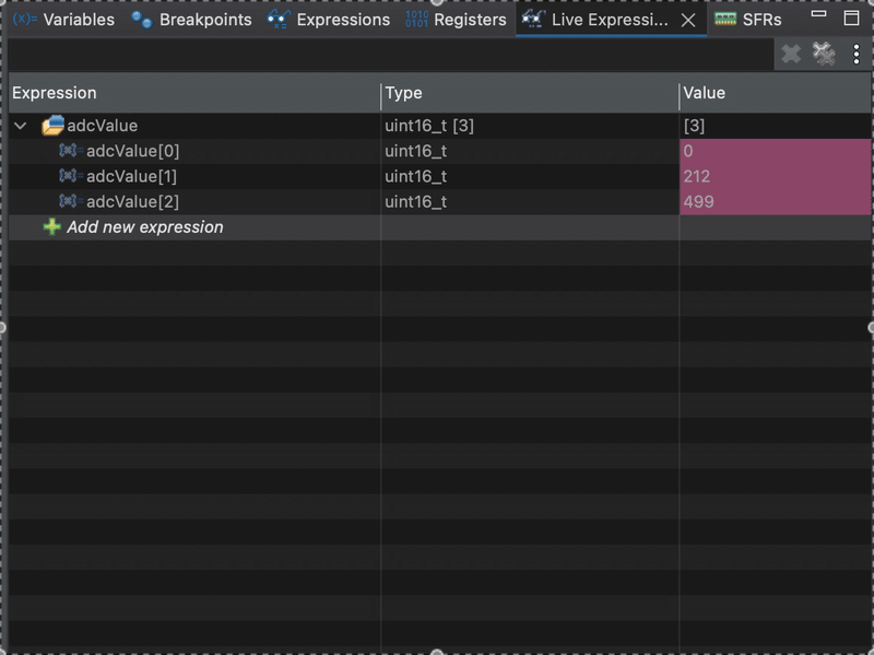
Start a debug session and add adcValue to live expression and you should the following:
Next part, we shall use interrupt and DMA to acquire the three channels effectively.
Happy coding 😉
Add Comment