
In the previous guide (here), we took a look how to configure the ADC in STM32F7 for single channel single conversion. In this guide, we shall configure the ADC in continuous mode conversion.
In this guide, we will cover the following:
- Difference between Single Conversion and Continuous Conversion.
- What extra steps needed to enable continuous mode.
- Connection diagram
- Code
- Results
1. Difference between Single Conversion and Continuous Conversion
In the single conversion mode, the ADC does one conversion and stop as soon as the conversion ended. The process can’t started unless the start is triggered by software. This can be useful for certain application like monitor battery capacity like every 10 minutes.
In continuous conversion mode, the ADC starts a new conversion as soon as it finishes one. This mode has the advantage of keeping the ADC value up to date for control purposes such as temperature, flow rate etc.
2. What the extra steps needed to enable Continuous Conversion
As we saw from the previous guide, we enabled the adc manually every time we needed to get a new adc value. To enable continuous mode, we need to enable CONT_bit (Bit 1) in Control Register 2 (CR2).
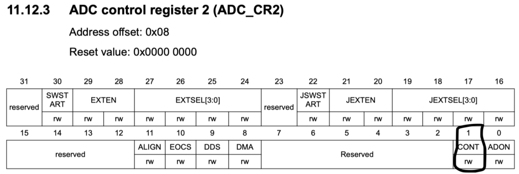
ADC1->CR2|=ADC_CR2_CONT;
Also, The SWSTART shall be set in the initialization function of the ADC.
3. Connection diagram:
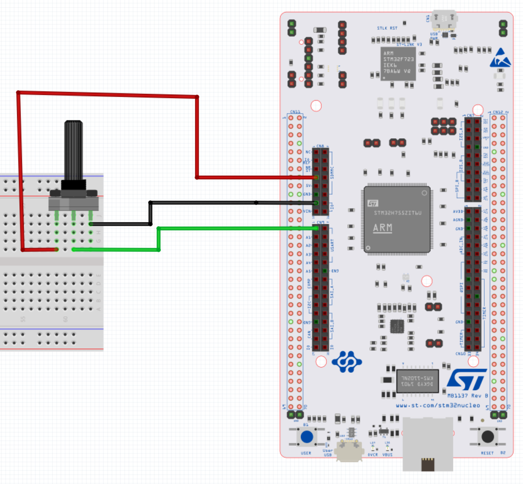
The connection is as following:
- Right leg of the pot to 3V3
- Middle leg to A0 of Arduino connection (PA3)
- Left leg to GND
4. Code:
#include "stm32f7xx.h"                  // Device header
#define CH3 0x03

uint16_t adc_data;

int main(void)
	{
	RCC->AHB1ENR|=RCC_AHB1ENR_GPIOAEN;
	RCC->APB2ENR|=RCC_APB2ENR_ADC1EN;

	GPIOA->MODER|=GPIO_MODER_MODER3_0|GPIO_MODER_MODER3_1;
	ADC1->SQR1=0;
	ADC1->SQR3|=(CH3<<0);
	ADC1->CR2|=ADC_CR2_CONT;
	ADC1->CR2|=ADC_CR2_ADON;
	ADC1->CR2|=ADC_CR2_SWSTART;
	while(1)
		{
		while(((ADC1->SR) & ADC_SR_EOC) == 0);
		adc_data=ADC1->DR;
		for (volatile int i=0;i<10000;i++);
		}
	}
5. Results:
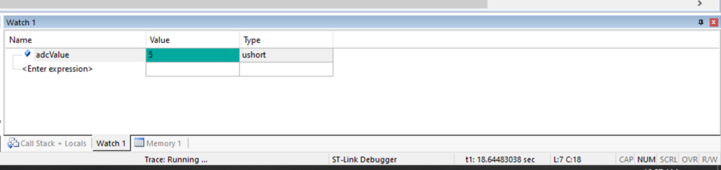
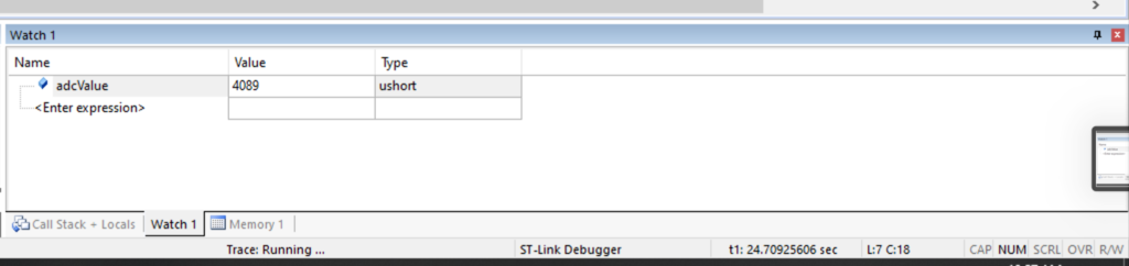
After compiling the code, uploading the code to mcu, opening a debug session in keil uVision
Rotate the potentiometer and observe the adc_data in watch window
Happy coding 😊😊
Add Comment