In the pervious guide (here), we took a look at how to control stepper motor. This guide is about DC motor interfacing with STM32F411 Nucleo-64. We will learn to control the speed of a DC motor using a pulse width modulation module (PWM) of STM32F411 and L298N motor driver modules. Furthermore, we will also control the direction of rotation of a motor using the built-in H-bridge of L298N and GPIO pins of STM32F411 microcontroller. We will use Keil uvision to write a program and upload code to STM32F411.
In this guide, we will cover the following:
- DC-Motor
- L298 Motor driver
- Connection
- Code
- Demo
1.1 DC Motor:
DC motors are electro-mechanical machines which convert electrical energy into mechanical (rotational) energy. If you are looking to develop a robot such as a line follower robot, obstacle avoidance robot, these DC motors will be the first choice for you. They are available in direct drive or geared types. But, both types require a dc voltage to operate. Therefore, we apply a DC voltage to drive DC motors.
1.2 Speed Control
The speed of rotation of motors is directly related to the input voltage. The higher the input voltage, the higher will be the rotational speed of the motor. But the voltage should be within the operating voltage range.
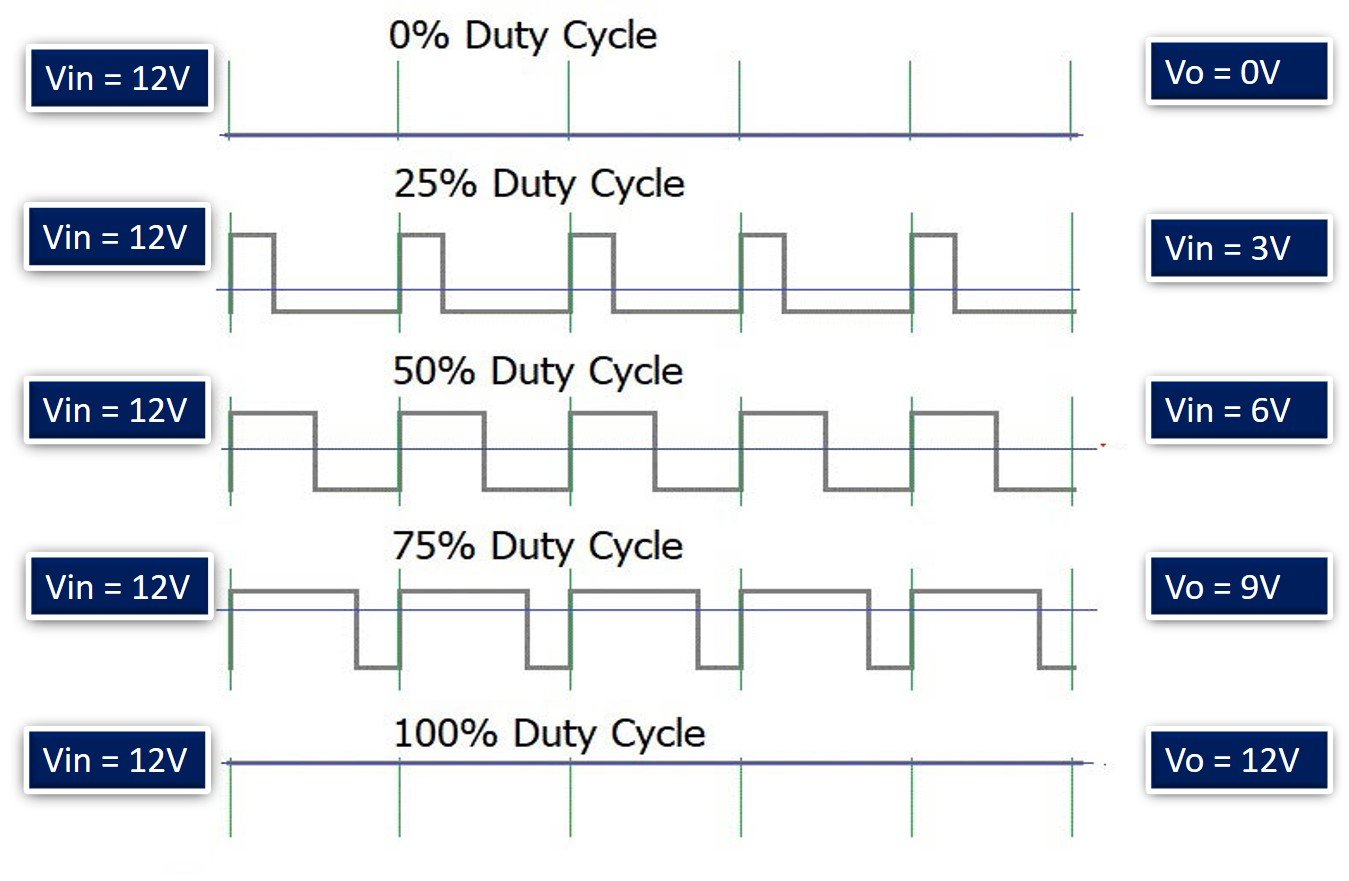
One important point to note here is that if we want to control the speed of a DC motor, we will need to provide a variable voltage to the DC motor. For example, If the operating voltage range of a motor is between 3 – 6 volts. If we apply 3 volts input, the motor will run at its lowest rated speed. Similarly, if we apply 6 volts, the DC motor will run at its highest rated speed. In short, we can control the speed of rotation by giving a variable input voltage to a DC motor. Usually, a pulse width modulation technique is used to generate a variable dc voltage from constant dc voltage source. We will discuss it in later sections of this tutorial.
1.3 Direction Control
As you know that in case of DC power supply, there is a concept of polarity such as positive and negative terminals of a battery. The polarity of input voltage source determines the direction of rotation of a DC motor. For instance, if we connect the positive terminal of battery with one terminal and the negative terminal of battery with another terminal of DC motor, it will start rotating in clockwise direction. But if we interchange the connection of the battery by connecting opposite polarity, the DC motor will start rotating in another direction.
For more details how the DC motors works and what you should considered when driving, take look at this video
2.1 L298N Motor driver
L298N motor driver IC has many applications in the embedded field, especially on the robotics side. Most of the microcontrollers operate on very low voltage (5v) and current while the motors require higher voltages and current So, the microcontrollers cannot provide them such higher current. For this purpose, we use motor driver ICs.
2.2 Features of the L298N motor driver Module
298N is an integrated circuit multi watt 15 package and capable of giving high voltage. It is a high current dual full-bridge driver that is designed to accept standard TTL logic levels. It can drive inductive loads e.g relays, solenoids, motors (DC and stepping motor), etc.
Its basic features are:
- Maximum supply voltage 46V
- Maximum output DC current 4A
- Low saturation voltage
- Over-temperature protection
- Logical “0” Input Voltage up to 1.5 V
PIN DIAGRAM of L298N
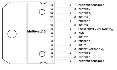
The pin diagram in top view for L298N is given below:
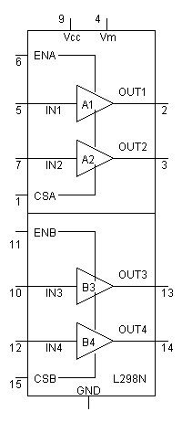
Motor Driver Internal Circuit
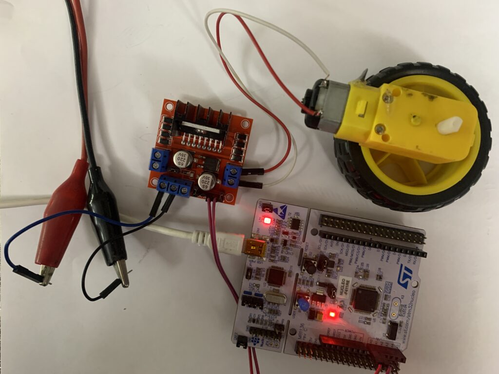
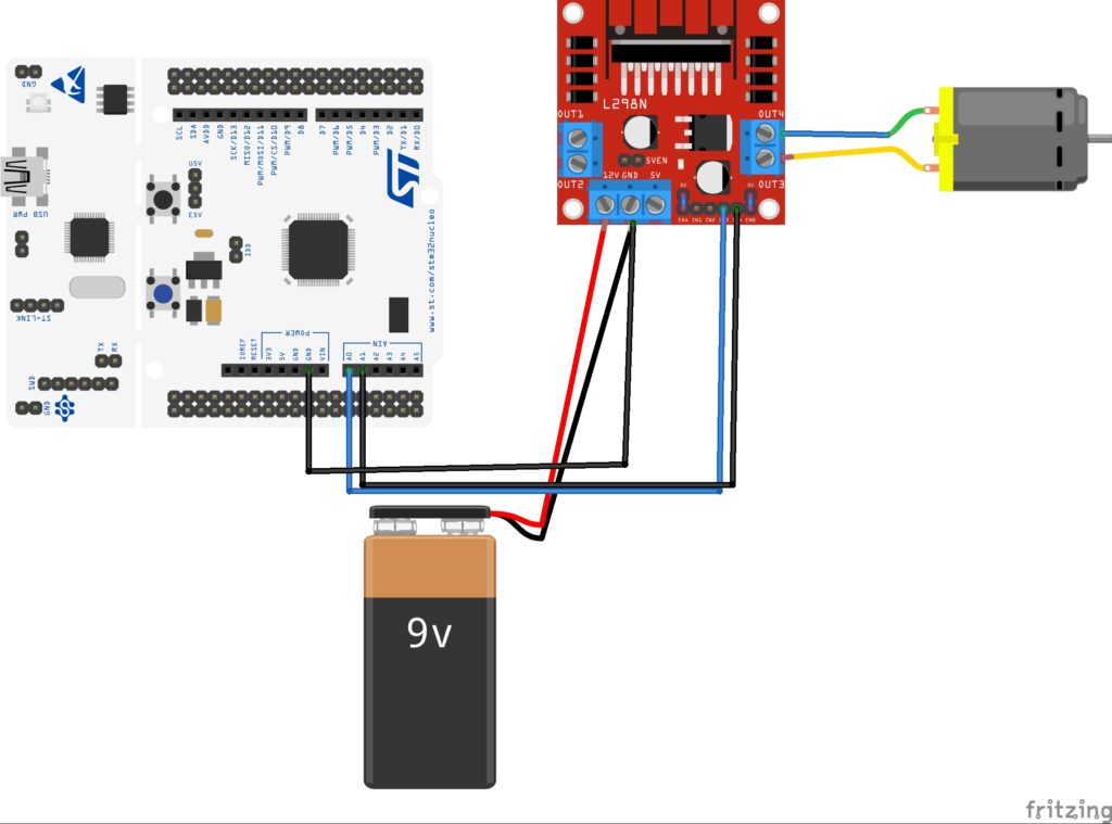
3. Connection:
For this guide, we shall use TIMER2 of STM32F411RE to control the speed and direction of the DC motor. Hence, we are using PA0 and PA1 to to IN3 and IN4 (or IN1 and IN2) of L298N motor driver motor as shown in figure below:
4. Code:
For how to configure the TIMER2 of STM32F4 as PWM, refer to this guide (Link).
The code:
#include "stm32f4xx.h"                  // Device header
void GPIO_Init(void);
void Timer2_init(void);
void delay(int ms );
#define rate 255
int main(void)
{

GPIO_Init();
Timer2_init();
while(1)
{
for (int i=0;i<rate;i++){
TIM2->CCR1=i;
TIM2->CCR2=0;
delay(5);
}
delay(1000);
for (int i=255;i>0;i--){
TIM2->CCR1=i;
TIM2->CCR2=0;
delay(5);
}
delay(1000);

for (int i=0;i<rate;i++){
TIM2->CCR1=0;
TIM2->CCR2=i;
delay(5);
}
delay(1000);
for (int i=255;i>0;i--){
TIM2->CCR1=0;
TIM2->CCR2=i;
delay(5);
}
delay(1000);

}
}

void GPIO_Init(void)
{
RCC->AHB1ENR|=RCC_AHB1ENR_GPIOAEN;
GPIOA->AFR[0]|=(1<<0)|(1<<4);
GPIOA->MODER|=(1<<1)|(1<<3);

}
void  Timer2_init(void){
RCC->APB1ENR|=RCC_APB1ENR_TIM2EN; //enable clock access tto tim2
TIM2->PSC=0; //set prescaller to 0 (no divider)
TIM2->ARR=rate; //set the maximum count value
TIM2->CNT=0; //seset the current count
TIM2->CCMR1=(1<<5)|(1<<6)|(1<<13)|(1<<14); //configure the pins as PWM
TIM2->CCER|=0x11; //enbale channel1 and channel2
TIM2->CR1=1; //enable timer
}


void delay(int ms)

{

int i;

for(; ms>0 ;ms--)

{

for(i =0; i<3195;i++);

}

}
4 Comments
How to control the speed of bldc motor using stm32f401re based on the POT
Hi,
check this:
https://blog.embeddedexpert.io/?p=2377
Modify the code according to your requirements.
how to write the same code in proteus
Hi,
Proteus won’t reflect the real world usage.
It might work in Proteus but in reality, it won’t.
Add Comment