In this guide, we shall take a look at BLDC and how to control the speed of the BLDC using STM32F4.
In this guide, we shall cover the following:
- What is BLDC Motor.
- Construction of the BLDC Motor and how it works.
- Connection of the BLDC Motor with ESC and STM32.
- Driver.
- Results.
1. What is BLDC Motor:
A Brushless DC motor (BLDC), also known as an electronically commutated motor, is a type of synchronous motor that operates using a direct current (DC) electric power supply. Unlike traditional brushed DC motors, BLDC motors do not have brushes. Instead, they utilize an electronic controller to switch DC currents to the motor windings, creating magnetic fields that effectively rotate in space. The permanent magnet rotor then follows these magnetic fields.
Here are some key points about BLDC motors:
- Working Principle:
- BLDC motors use electronic commutationto control the motor’s speed and torque.
- The controller adjusts the phase and amplitude of the DC current pulses to achieve precise control.
- This electronic control system replaces the mechanical commutator (brushes) found in conventional electric motors.
- Advantages of BLDC Motors:
- High power-to-weight ratio: BLDC motors are lightweight and powerful.
- High speed: They can operate at high rotational speeds.
- Instantaneous control: BLDC motors respond quickly to changes in speed and torque.
- High efficiency: They minimize energy loss.
- Low maintenance: No brushes means less wear and tear.
2. Construction of BLDC Motor and How It Works:
For detailed information about this, please check this youtube video:
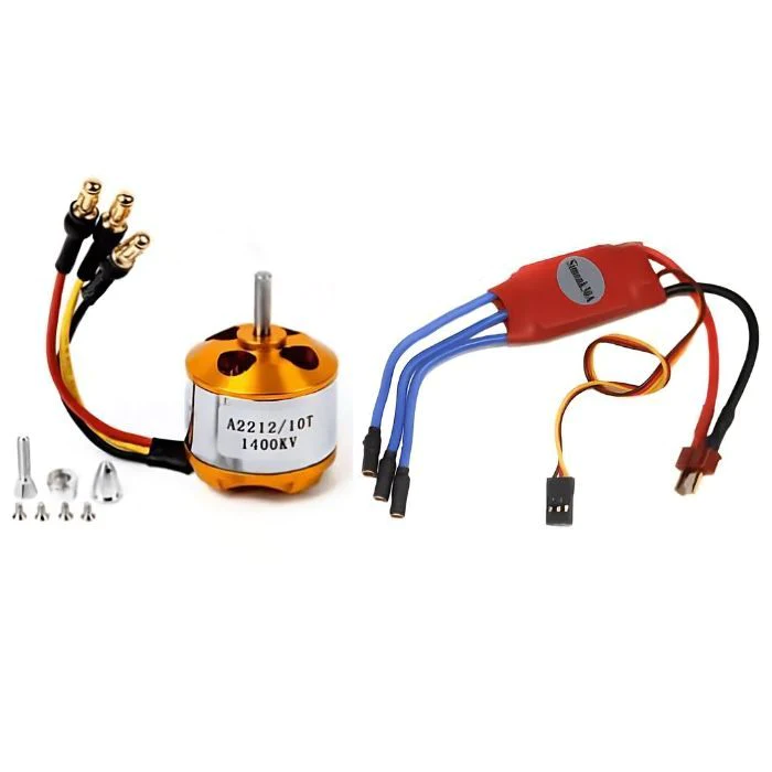
3. Connection of the BLDC and ESC with STM32:
The connection as following:

When connecting the BLDC to ESC, make sure that the middle wire of BLDC is connected to the middle wire of the ESC. The other two can be connected in any direction. However, this will effect the rotation of the BLDC.
The connection of control pins as following:
| ESC | STM32F4xx |
| PWM (Orange) | PA0 |
| GND (Brown) | GND |
Note: The red wire (5V) will provide 5V in case you want to power the MCU from external 5V power supply.
4. Developing the Drivers:
Since this type of ESC requires standard 50Hz PWM signal with length of 1 to 2ms to control the speed, which is similar to servo signal which already developed driver for it here.
We start off by creating new source and header file with name of bldc.c and bldc.h respectively.
Within the header file, include the header guard as following:
#ifndef BLDC_H_
#define BLDC_H_


#endif /* BLDC_H_ */
Include stdint library:
#include "stdint.h"
Declare the following functions:
/* @Brief This function shall initial GPIOA Pin 0 to control the BLDC motor
 * @Param Nothing
 * @Return Nothing
 * */
void BLDC_Pin_Init(void);

/* @Brief This function shall initial TIM2 of STM32F4 to generate 50Hz PWM signal
 * @Param freq which is the bus frequency that connected to TIM2 in MHz
 * @Return Nothing
 * */
void BLDC_TIM2_Init(uint16_t freq);


/* @Brief This function shall set the speed of the BLDC motor
 * @Param speed in percentage
 * @Return nothing
 * */
void BLDC_SetSpeed(uint8_t speed);


/* @Brief This function shall calibrate the ESC for the pulses
 * @Param nothing
 * @Return nothing
 * */
void BLDC_Calibrate(void);
For the source file:
Include the following header files
#include <bldc.h>
#include "stm32f4xx.h"
#include "delay.h"
For the BLDC pin initialization:
void BLDC_Pin_Init(void)
{
	#define TIM2_AF 0x01
	/*Enable clock access to GPIOA*/
	RCC->AHB1ENR|=RCC_AHB1ENR_GPIOAEN;

	/*Set PA0 to alternate function*/
	GPIOA->MODER|=GPIO_MODER_MODE0_1;
	GPIOA->MODER&=~GPIO_MODER_MODE0_0;

	/*Set the GPIO speed to maximum*/
	GPIOA->OSPEEDR|=GPIO_OSPEEDER_OSPEEDR0;

	/*Set which alternate function */
	GPIOA->AFR[0]|=(TIM2_AF<<GPIO_AFRL_AFSEL0_Pos);

}
For the timer initialization:
void BLDC_TIM2_Init(uint16_t freq)
{
	/*Enable clock access to TIM2*/
	RCC->APB1ENR|=RCC_APB1ENR_TIM2EN;

	/*Set the PSC and ARR values*/
	TIM2->PSC=freq-1;
	TIM2->ARR=20000-1;

	/*Set TIM2_CH1 as PWM */

	TIM2->CCMR1|=TIM_CCMR1_OC1M_2|TIM_CCMR1_OC1M_1;

	/*Enable TIM2_CH1*/
	TIM2->CCER|=TIM_CCER_CC1E;

	/*Set TIM2_CH1 to 1ms (1000)*/
	TIM2->CCR1=0;

	/*Enable TIM2*/

	TIM2->CR1|=TIM_CR1_CEN;

}
So far, it is similar to the servo motor initialization.
Now, we declare a static function that will convert the speed to duty cycle value as following:
/* @Brief This function shall calculate the duty cycle according the required speed
 * @Param speed in percentage
 * @Return duty cycle for the required speed
 * */

static long speedt_to_duty(uint8_t speed)
{
  return (10*speed +1000);
}
For set speed function:
void BLDC_SetSpeed(uint8_t speed)
{
	if (speed >100){speed=100;}

	/*Set the duty cycle according to the calculation*/
	TIM2->CCR1=speedt_to_duty(speed);
}
Some ESC has the ability to be calibrated for the signal, hence the function to calibrate the ESC as following:
void BLDC_Calibrate(void)
{
	TIM2->CCR1=1000;
	delay(3000);
	TIM2->CCR1=2000;
	delay(3000);
	TIM2->CCR1=0;
}
The steps as following:
- Send the lowest required signal.
- Wait for 3 seconds.
- Send the maximum required signal.
- Wait for 3 seconds.
- set the duty cycle to 0.
In main.c file:
#include <bldc.h>
#include "delay.h"
int speed;
int main(void)
{

	BLDC_Pin_Init();
	BLDC_TIM2_Init(16);
	delay_init(16000000);
	BLDC_Calibrate();

	while(1)
	{
		for (speed = 0; speed <= 100; speed += 1)
		{
				BLDC_SetSpeed(speed);
		    delay(15);
		}
		delay(500);
		for (speed = 180; speed >= 0; speed -= 1)
		{
				BLDC_SetSpeed(speed);
		    delay(15);
		}
		delay(500);


	}

}
5. Results:
Happy coding 🙂
4 Comments
Hello my teacher
nice work,
thank you for sharing
Welcome
Teacher this is great, is there any possibility that you can do a tutorial of the whole thing you have in your final video? like the box with a knob and the information of the shown in the display?
The white box is just power supply I made.
Add Comment