In pervious PWM guide (here), discussed how to use TIM2 of STM32F411 to generate 2 PWM signals to fade 2 LEDs. In this guide, we shall use PWM signal to control a servo motor (SG90).
In this guide, we shall cover the following
- What is servo motor and how to control it
- Connection
- Code
- Demo
1. What is servo motor and how to control it
A servomotor is a rotary actuator or linear actuator that allows for precise control of angular or linear position, velocity and acceleration.[1] It consists of a suitable motor coupled to a sensor for position feedback. It also requires a relatively sophisticated controller, often a dedicated module designed specifically for use with servomotors. (Wikipedia link).
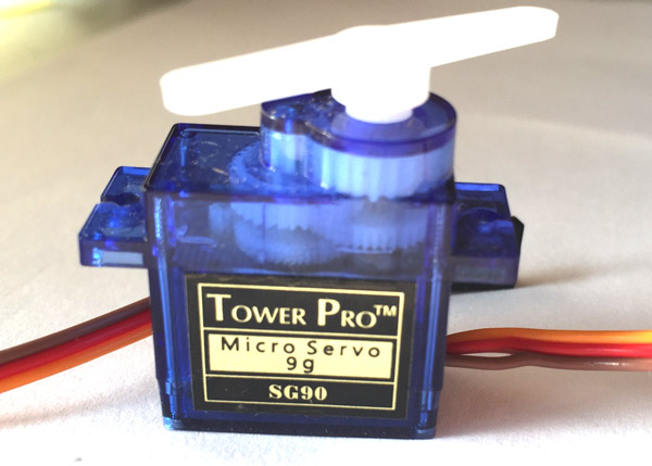
The servo motor used in our guide has three wires: red, brown and orange.
| Wire color | Function |
| Red | Vcc (4~6V) |
| Brown | GND |
| Orange | Signal |

In order to control the angle of the servo motor, a PWM signal of frequency 50Hz (20mS period) needed to be applied to the signal pin on the servo motor. to determine the angle of the servo as following:
| Angle | Duty Cycle (Period) |
| 0 | 5% (1mS) |
| 90 | 7.5% (1.5mS) |
| 180 | 10%(2mS) |
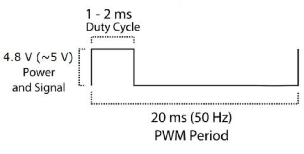
Hence we need to configure the TIM2 to generate 50Hz PWM signal on PA0 pin
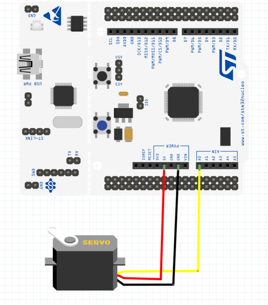
2. Connection:
In this guide, we need the following
- STM32F411 Nucleo
- SG90 microservo
- Hock-up wires
3. Code:
#include "stm32f4xx.h"                  // Device header
void GPIO_Init(void);
void Timer2_init(void);
void delay(int ms );
void servo_write(uint8_t angle);

int pos;
int main(void)
{

GPIO_Init();
Timer2_init();
while(1)
{
for (pos = 0; pos <= 180; pos += 1) { // goes from 0 degrees to 180 degrees
    // in steps of 1 degree
    servo_write(pos);              // tell servo to go to position in variable 'pos'
    delay(15);                       // waits 15ms for the servo to reach the position
  }
  for (pos = 180; pos >= 0; pos -= 1) { // goes from 180 degrees to 0 degrees
    servo_write(pos);              // tell servo to go to position in variable 'pos'
    delay(15);                       // waits 15ms for the servo to reach the position
  }

}
}

void GPIO_Init(void)
{
RCC->AHB1ENR|=RCC_AHB1ENR_GPIOAEN;
GPIOA->AFR[0]|=(1<<0);
GPIOA->MODER|=(1<<1);

}
void  Timer2_init(void){
RCC->APB1ENR|=RCC_APB1ENR_TIM2EN; //enable clock access tto tim2
TIM2->PSC=4; //set prescaller to 4 (16000000Hz/4=4000000Hz)
TIM2->ARR=63999; //set the maximum count value
TIM2->CNT=0; //seset the current count
TIM2->CCMR1=(1<<5)|(1<<6); //configure the pins as PWM
TIM2->CCER|=0x1; //enbale channel1 and channel2
TIM2->CR1=1; //enable timer
}


void delay(int ms)

{

int i;

for(; ms>0 ;ms--)

{

for(i =0; i<3195;i++);

}

}

long map(long x, long in_min, long in_max, long out_min, long out_max)
{
  return (x - in_min) * (out_max - out_min) / (in_max - in_min) + out_min;
}


void servo_write(uint8_t angle)
	{

	if(angle<0){angle=0;}
	if(angle>180){angle=180;}


TIM2->CCR1=map (angle,0,180,2500,7000);


	}
4 Comments
Thanks for your nice and kind helping me and spends alot of time to prepare EmbeddedExpertIO site Mr Husamuldeen.
May ı ask a question for you.
How can we run the program to my card f429 or f407, f103. Can you explain me
Thanks
God bless you
Huseyin AKGUL
Elektronik-Software
Ankara TURKIYE
For STM32F4xx, it will be the same.
For F103, it will be similar with minor modification.
Check this for how to generate PWM signal using F103:
https://blog.embeddedexpert.io/?p=1400
Hi friend
I am using a STM32L053R8
I had to change the line:
RCC->AHB1ENR|=RCC_AHB1ENR_GPIOAEN;
but I have an error when running the program, when the motor starts to work it does so slowly and does not oscillate between 0 and 180
Do you have any idea why this happens?
Hi,
this is how to generate PWM on STM32L0:
https://blog.embeddedexpert.io/?p=1012
Add Comment