In the previous guid (here), the timer interrupt was introduced with rate of 1Hz to blink the LED.In this guide, it shall present the usage of timer in PWM mode. This guide shall cover the following:
- What is PWM.
- Configure the timer and GPIO to generate PWM signal.
- Connection.
- Code.
- Demo.
1. What is PWM:
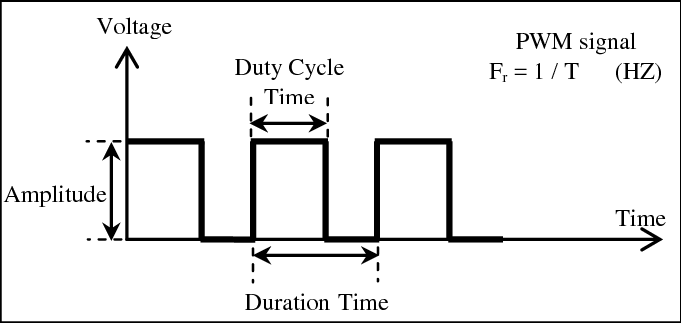
PWM is a technique used to emulate “analog signal” by rapidly turning on-off the pin. This allow the mcu to vary the power delivered to the load such as motor (will be covered later). The PWM has three main characteristics;
- Frequency:
which describe the duration time of the entire signal
- Duty cycle
The term duty cycle describes the proportion of ‘on’ time to the regular interval or ‘period’ of time; a low duty cycle corresponds to low power, because the power is off for most of the time. Duty cycle is expressed in percent, 100% being fully on.
- Amplitude
Which is the voltage level of the PWM (3.3v for STM32L0).
For more details, please check this wikipedia article (here).
2. Configure the timer and GPIO to generate PWM Signal:
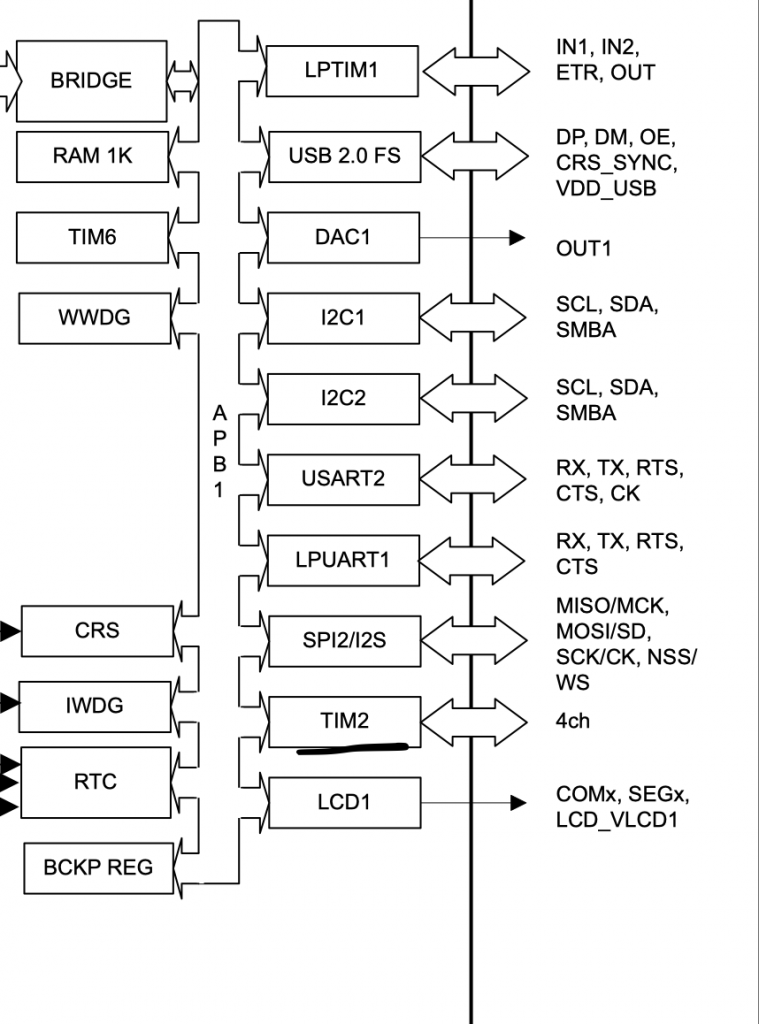
First we need to locate which pins connected to TIMER2_CH1 and TIMER2_CH2.
From the datasheet, we can find the related timer channels:
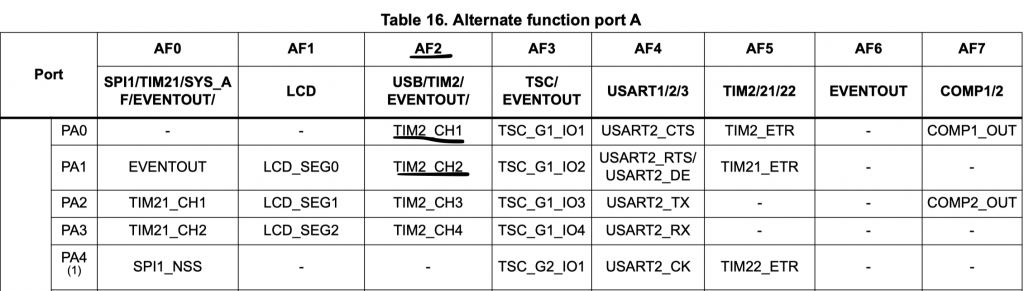
From the datasheet, the pins are related to timer1 are PA0 and PA1 and also the alternative function is AF2 and we can create a symbolic name as following:
#define TIM2_AF 0x02
Then we can enabled clock access to GPIOA as following:
In order to enable clock access to the GPIOA, we need to go to reference manual and check the register named GPIO clock enable register.
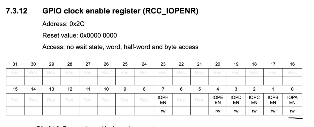
Hence, we need to set bit0 to 1 and we can use CMSIS macros to do it as following:
	/*Enable clock access to GPIOA*/
	RCC->IOPENR |= RCC_IOPENR_GPIOAEN;
Then we shall set the mode of the pin to be alternate fuction:
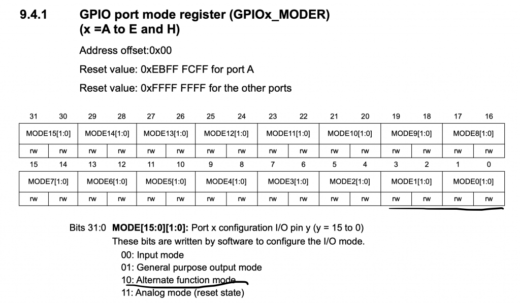
	/*Set PA0 and PA1 to alternate function*/
	GPIOA->MODER|=GPIO_MODER_MODE0_1|GPIO_MODER_MODE1_1;
	GPIOA->MODER&=~(GPIO_MODER_MODE0_0|GPIO_MODER_MODE1_0);
Then set which alternate function shall be used from GPIO alternate function low register (AFR[0]):
	/*Select which alternate function*/
	GPIOA->AFR[0]|=(TIM2_AF<<0)|(TIM2_AF<<4);
Now we can configure the timer to generate PWM signal
We start off by enabling clock access to TIMER2 as following:
RCC->APB1ENR|=RCC_APB1ENR_TIM2EN;
Set the prescaler and ARR to 0 & 100 respectively:
	TIM2->PSC=0;
	TIM2->ARR=100;
In order to configure the timer to work in PWM, this where TIM capture/compare mode register 1 will come to play, this register responsible to CH1 and CH2.
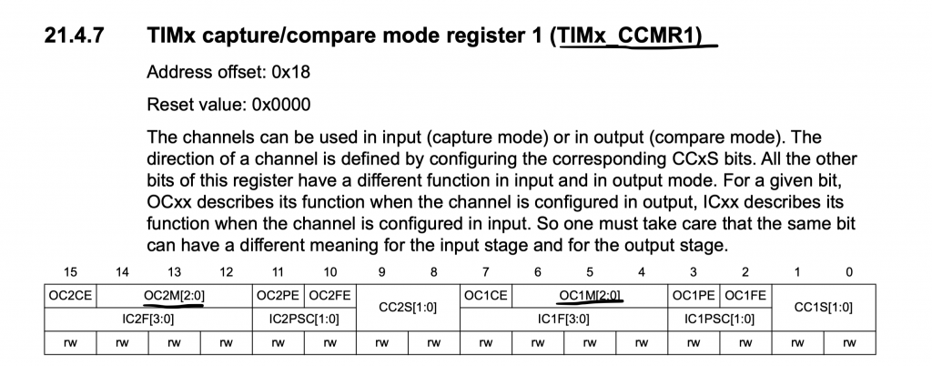
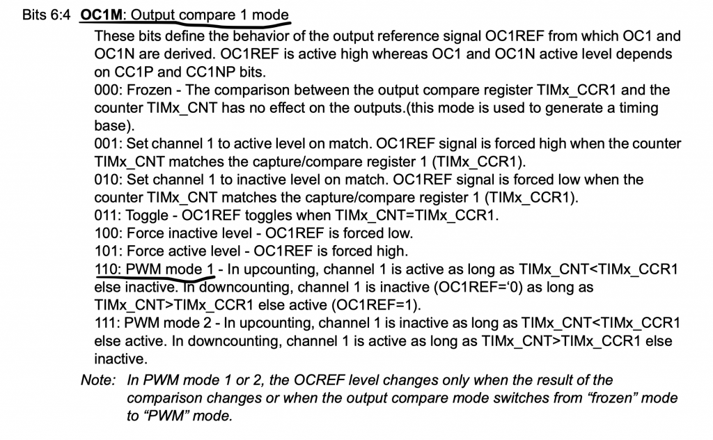
Hence, bit 5 and 6 for CH1 to be in PWM mode, bit 13 and 14 for CH2 to be in PWM mode.
TIM2->CCMR1|=TIM_CCMR1_OC1M_2|TIM_CCMR1_OC1M_1|TIM_CCMR1_OC2M_2|TIM_CCMR1_OC2M_1;
Then, capture compare shall be enabled:
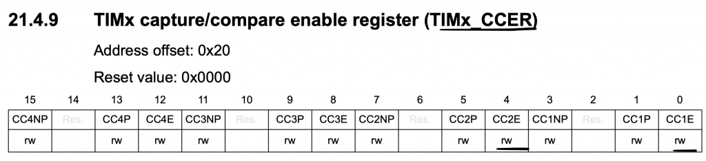
TIM2->CCER|=TIM_CCER_CC1E|TIM_CCER_CC2E;
Finally enable the timer:
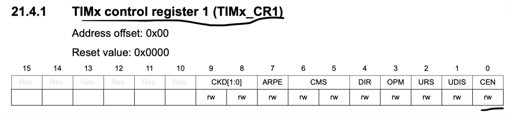
TIM2->CR1|=TIM_CR1_CEN;
In the header file, we can define an enum to distinguish the channel :
typedef enum
	{

	CH1=0,
	CH2=1
	}PWM_CH;
In order to update each channel separately:
We shall use dedicated function:
void update_duty_cycle(PWM_CH ch, uint16_t duty )
	{
	uint16_t max_duty=TIM2->ARR; /*Limit the Duty cycle to ARR maximum value*/
	if(duty>max_duty){duty=max_duty;}
	switch (ch)
	{
		case CH1: TIM2->CCR1=duty; break;
		case CH2: TIM2->CCR2=duty; break;
		default: break;

	}

	}
Hence, the header file as following:
#ifndef TIM_H_
#define TIM_H_

#include "stdint.h"

typedef enum
	{

	CH1=0,
	CH2=1
	}PWM_CH;


void tim2_pwm();

void update_duty_cycle(PWM_CH ch, uint16_t duty );


#endif /* TIM_H_ */
The source file file:
#include "tim.h"

#include "stm32l0xx.h"

#define TIM2_AF 0x02


void tim2_pwm()
	{


	/*Enable clock access to GPIOA*/
	RCC->IOPENR |= RCC_IOPENR_GPIOAEN;
	/*Set PA0 and PA1 to alternate function*/
	GPIOA->MODER|=GPIO_MODER_MODE0_1|GPIO_MODER_MODE1_1;
	GPIOA->MODER&=~(GPIO_MODER_MODE0_0|GPIO_MODER_MODE1_0);
	/*Select which alternate function*/
	GPIOA->AFR[0]|=(TIM2_AF<<0)|(TIM2_AF<<4);

	/**Configure timer 2 in PWM mode */

	RCC->APB1ENR|=RCC_APB1ENR_TIM2EN;
	TIM2->PSC=0;
	TIM2->ARR=100;
	TIM2->CCMR1|=TIM_CCMR1_OC1M_2|TIM_CCMR1_OC1M_1|TIM_CCMR1_OC2M_2|TIM_CCMR1_OC2M_1;
	TIM2->CCER|=TIM_CCER_CC1E|TIM_CCER_CC2E;
	TIM2->CR1|=TIM_CR1_CEN;

	}

void update_duty_cycle(PWM_CH ch, uint16_t duty )
	{
	uint16_t max_duty=TIM2->ARR; /*Limit the Duty cycle to ARR maximum value*/
	if(duty>max_duty){duty=max_duty;}
	switch (ch)
	{
		case CH1: TIM2->CCR1=duty; break;
		case CH2: TIM2->CCR2=duty; break;
		default: break;

	}

	}
The main loop:
#include "tim.h"
#include "stm32l0xx.h"
int main(void)
{
	tim2_pwm();

	while(1)
	{

			for (int i=0;i<=100;i++)
				{
					update_duty_cycle(CH1,i);
					update_duty_cycle(CH2,100-i);
					for (int j=0;j<1000;j++);

				}

			for (int i=100;i>=0;i--)
					{
						update_duty_cycle(CH1,i);
						update_duty_cycle(CH2,100-i);
						for (int j=0;j<1000;j++);

					}

	}

}
3. Code:
You may download the source code from here:
4. Demo:
Happy coding 🙂
5 Comments
Hey man! Thanks a lot, great tutorials. Could you continue your series on UART with stm32f767? Sending strings and using printf from stdio.h? I tried to add printf it from your previous tutorial but I get error when I addstruct __FILE {int handle;/* Add whatever*/}; It doesn’t recognize __FILE. Im loosing my haird trying to get printf work om my stmf767 via st-link. Thanks!
Hi,
change the compiler from v6 to v5 on keil uVision.
Thanks for your response. It doesn’t seem to work. I downloaded latest 5th version and it doesn’t even compile my led blink code. I came from microchip Studio and to set my UART there it takes a couple of minutes lol. Is there any way to get stdio.h work with v6? Point me, thank a lot.
Hi,
this guide uses STM32CubeIDE. Keil uVision needs the code generated by STM32CubeMX.
Ok, got it. Using printf function in keil without cube is kind of a task. Thanks one more time
Add Comment