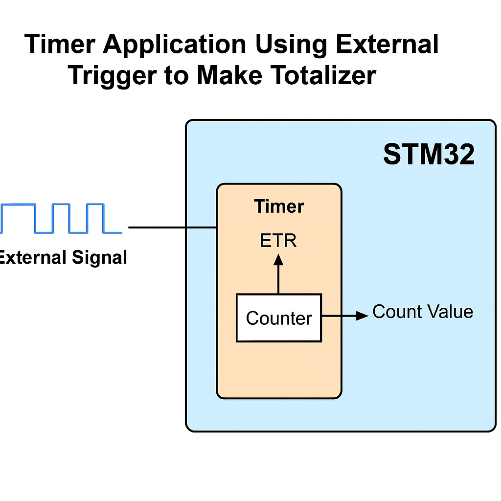
This application demonstrates how to configure an STM32 timer to use its External Trigger (ETR) input as the clock source, effectively turning the timer into a high-speed hardware totalizer. By feeding external pulses into the ETR pin, the timer counts each pulse directly in hardware, enabling accurate and efficient measurement of pulse-based quantities such as fluid flow, shaft rotations, or production events without burdening the CPU.
In this guide, we shall cover the following:
- Introduction.
- STM32CubeIDE setup.
- Firmware development.
- Connection.
- Results.
1. Introduction:
This guide presents a robust method for implementing a high-speed totalizer using the External Trigger (ETR) input of an STM32 timer. A totalizer is a fundamental component in many embedded and industrial systems, primarily used to count discrete events such as pulses generated by flow meters, rotary encoders, digital switches, or any other transducer that emits electrical pulses in response to physical actions. These counts can be used to calculate quantities such as fluid volume, distance traveled, production output, or mechanical revolutions, depending on the nature of the input signal and the sensor generating it.
Traditionally, pulse counting in embedded systems could be handled in software using GPIO interrupts or polling methods. However, as pulse frequency increases, this software approach becomes inefficient and unreliable due to limited processing speed, interrupt latency, or missed events during other critical tasks. The use of a hardware timer configured to count incoming pulses provides a highly efficient and accurate alternative, especially when coupled with the ETR (External Trigger) feature of STM32 timers.
In STM32 microcontrollers, many general-purpose and advanced-control timers include an ETR input pin that can be used as a dedicated external clock source. When the timer is configured in External Clock Mode 1, the ETR input effectively becomes the source of clock pulses for the timer’s counter. Each pulse on the ETR pin increments the timer’s internal counter automatically, completely offloading the CPU from having to process each individual event. This hardware-driven counting mechanism allows for extremely high-speed and reliable totalization of pulses, even under noisy or high-load conditions.
Another key advantage of using the ETR input for totalizing is the built-in flexibility and robustness it offers. STM32 timers allow configuration of the ETR input with digital filtering to suppress noise and debounce erratic signals. Additionally, the ETR path includes an optional prescaler that can divide down very high-frequency inputs to more manageable rates, which is useful when counting very fast pulses or when trying to extend the life of the counter before overflow. These features make the ETR-based totalizer highly suitable for harsh industrial environments, such as those found in manufacturing, energy systems, or process control.
To ensure long-term accuracy, especially in applications where large numbers of pulses are expected, the totalizer can be extended in software to 64 bits by tracking timer overflows through update interrupts. This approach allows developers to maintain an effectively unlimited count value, while still relying on the underlying hardware for fast and precise pulse detection.
In summary, configuring an STM32 timer in ETR mode provides a clean, reliable, and CPU-efficient solution for totalizing external pulses in real time. Whether you’re measuring fluid throughput, machine revolutions, or discrete process events, this method enables your embedded application to scale gracefully from simple counting tasks to complex, high-speed industrial metering systems. The remainder of this guide focuses on the hardware configuration and timer settings necessary to implement this solution. The software implementation, including overflow handling and data retrieval, is covered in the next sections.
2. STM32CubeIDE Setup:
Open STM32CubeIDE after selecting the workspace and create new project as following:

Select the MCU:

Give the project a name:
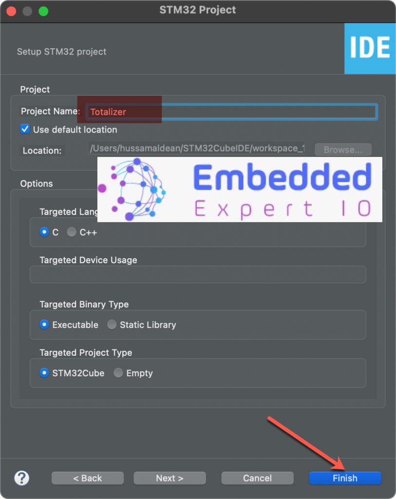
Click on Finish.
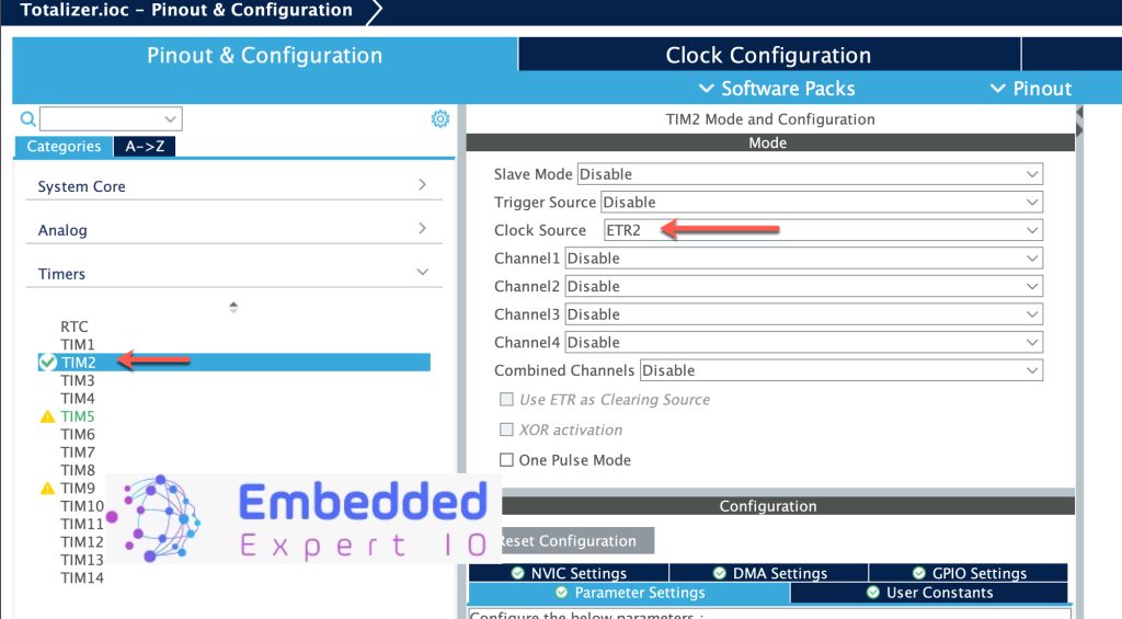
Next, STM32CubeMX window will appear, from timer configure TIM2 as follows:
- Clock Source to ETR2, this will set PA0 as ETR source for TIM2.
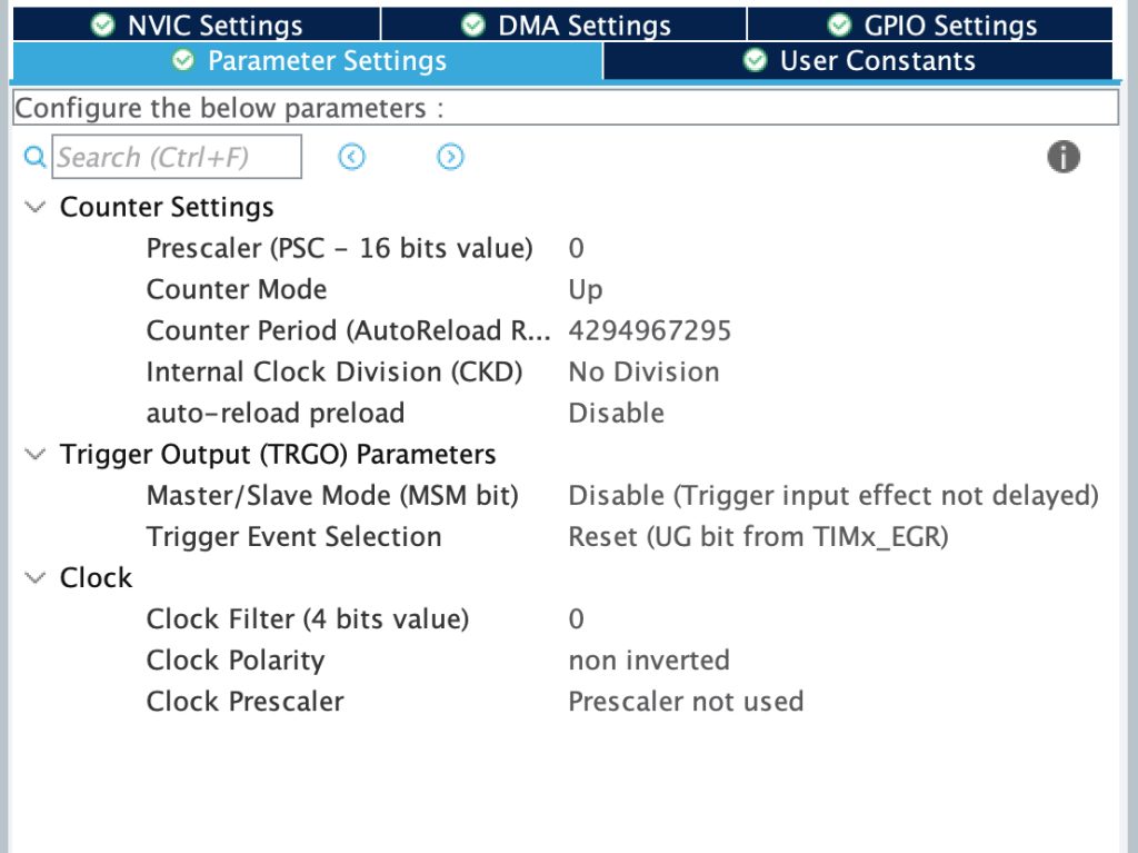
Leave the parameters settings as is:
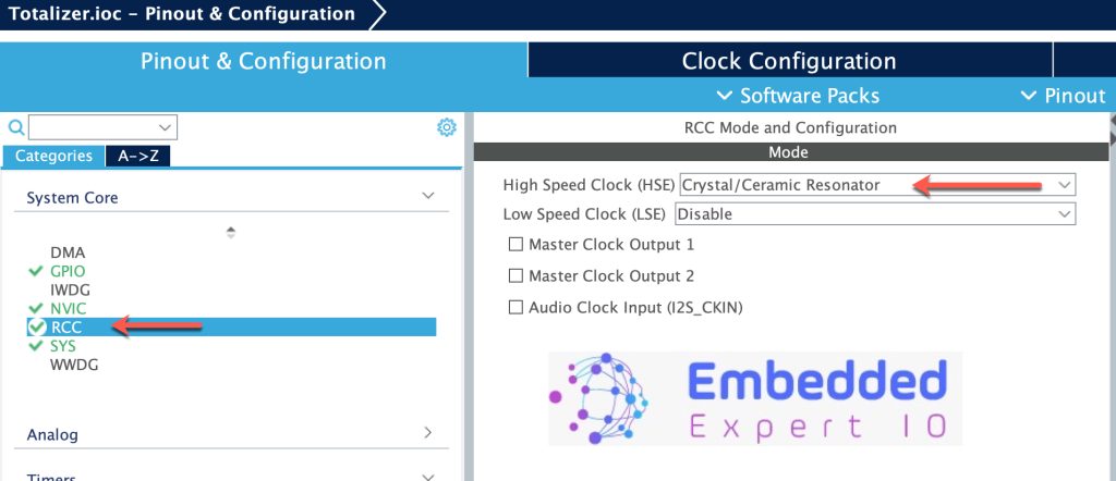
Next, from RCC, enable external oscillator as follows:
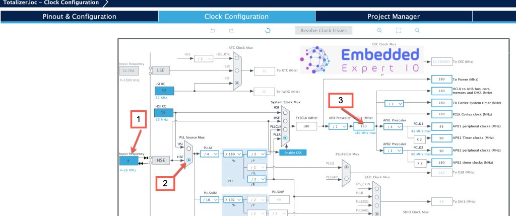
From clock configuration, configure the following:
- Set Input frequency according to your oscillator (8MHz in my case).
- Set PLL source to HSE.
- Set HCLK to maximum (180MHz in this case).
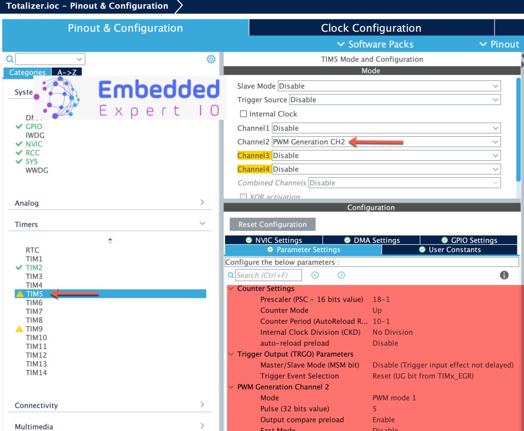
Next, set TIM5 Channel 2 as PWM as follows:
For more details how to configure timer in PWM mode, refer to this guide here.
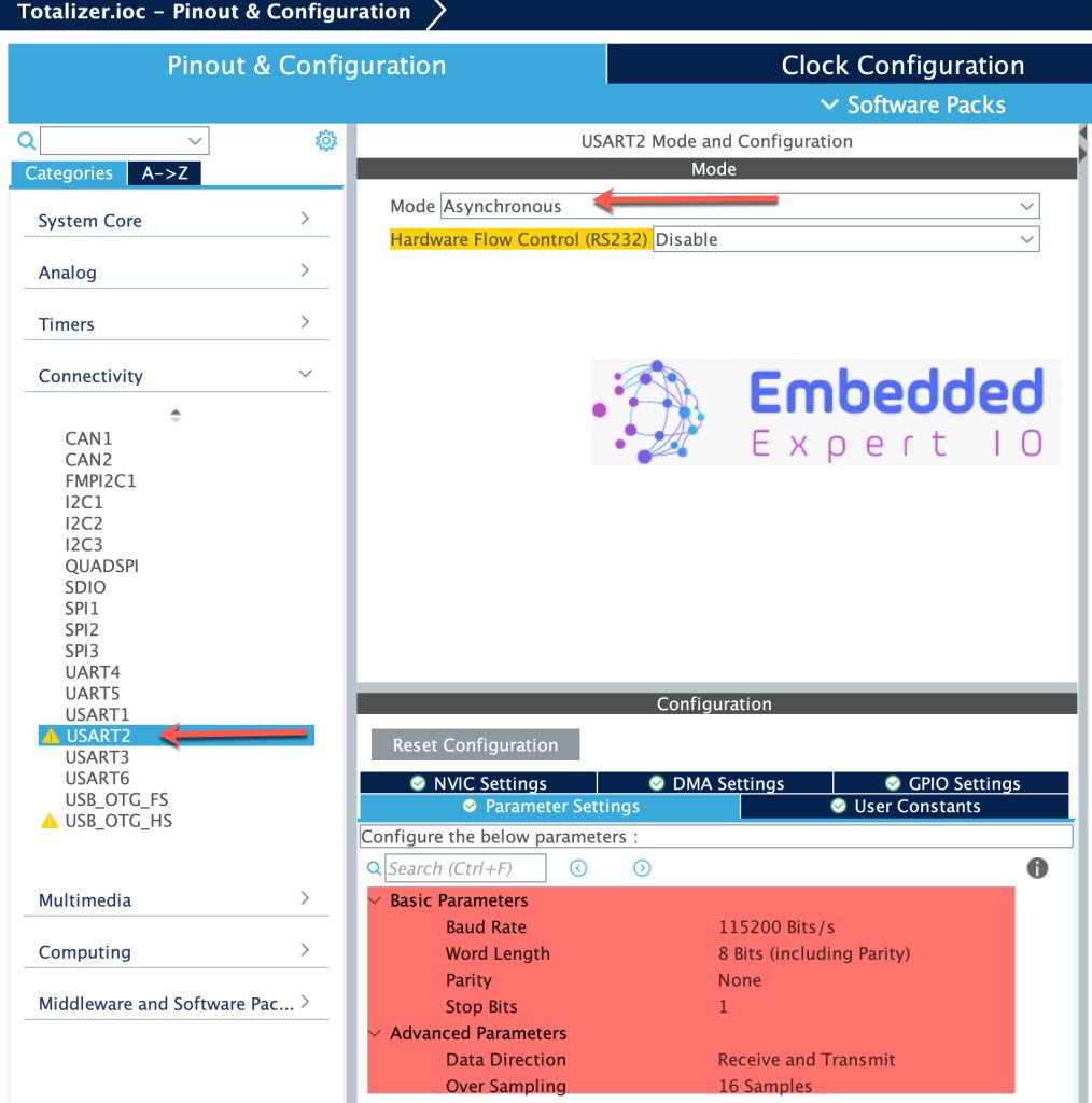
Also, enable UART to print the results as follows:
Thats all for the configuration. Save the project this will generate the project.
3. Firmware Development:
In user code begin includes, include stdio.h for printf.
#include "stdio.h"
In user code begin PV, declare the following variables:
volatile uint64_t totalizer;
volatile uint32_t last_cnt;
uint8_t uartBuffer[100]={0};
In user code begin 0, declare the following function:
uint64_t GetCounts(void)
{
	uint32_t current_cnt = __HAL_TIM_GET_COUNTER(&htim2);
	uint32_t delta;

	// Handle overflow (32-bit timer)
	if (current_cnt >= last_cnt)
		delta = current_cnt - last_cnt;
	else
		delta = (0xFFFFFFFF - last_cnt) + current_cnt + 1;

	totalizer += delta;
	last_cnt = current_cnt;

	return totalizer;
}
The function first reads the current timer counter and then compare it with the last value to handle the overflow situation of the timer.
Finally, return the totalized value.
In user code begin 2 in main function:
  HAL_TIM_Base_Start(&htim2);
  HAL_TIM_PWM_Start(&htim5, TIM_CHANNEL_2);
Start timer2 in base mode.
Start timer5 in PWM mode for channel 2.
In user code code begin 3 in while loop:
	  uint16_t len=sprintf(uartBuffer,"Totalizer Value = %u\r\n",GetCounts());
	  HAL_UART_Transmit(&huart2,uartBuffer,len,1000);
	  HAL_Delay(100);
Thats all for the firmware.
Build the project and run it.

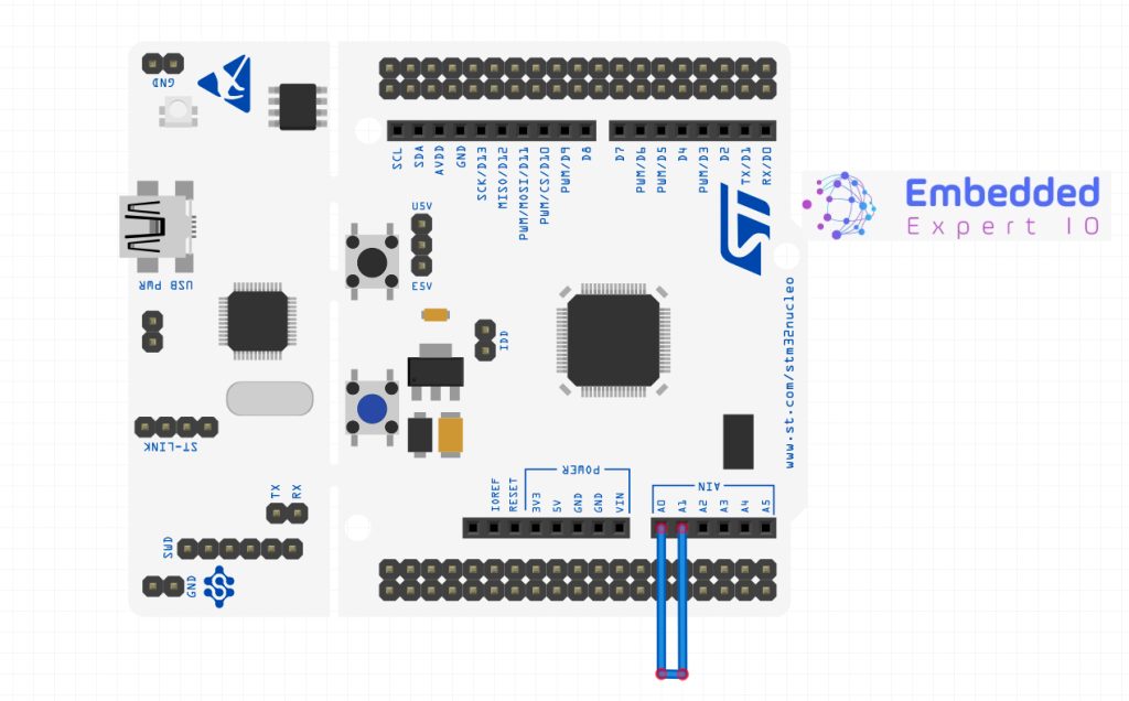
4. Connection:
The connection as simple as connecting jumper wires between PA0 and PA1. In case of Nucleo-64 board, connect A0 arduino pin to A1 Arduino pin as shown below:
5. Results:
Open your serial monitor application and set the baudrate to 115200 and you should get the following:
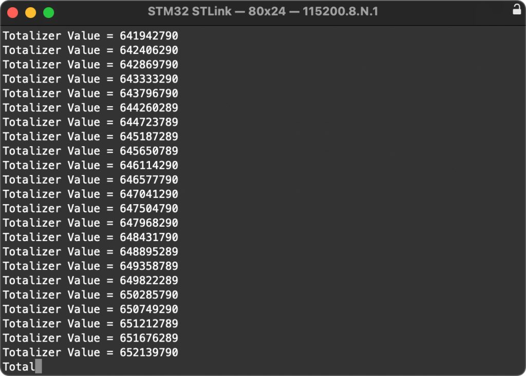
Happy coding 😉
Add Comment