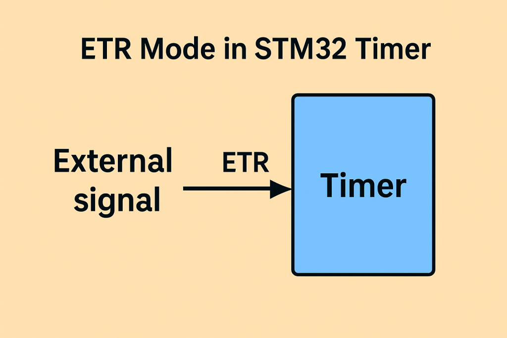
The External Trigger (ETR) mode in STM32 timers allows synchronization of timer operations with external events or signals, enabling precise timing control in real-time applications. This mode is especially useful when the timer needs to be started, gated, or clocked based on pulses or signals from external hardware like sensors, encoders, or other microcontrollers.
In this guide, we shall cover the following:
- Introduction.
- STM32CubeMX setup.
- Connection.
- Firmware development.
- Results.
1. Introduction:
The External Trigger (ETR) mode in STM32 timers is a powerful feature designed for applications requiring precise synchronization between internal timer functions and external events or signals. At its core, ETR mode enables the timer to be directly influenced or controlled by signals arriving from outside the microcontroller, offering developers a flexible way to integrate real-world event timing into embedded systems. This mode becomes particularly valuable in scenarios where timing accuracy, responsiveness to asynchronous events, or synchronization with external systems is paramount.
One of the primary benefits of ETR mode is its ability to act as a bridge between the microcontroller and the outside world, effectively allowing external pulses, clocks, or triggers to control the internal counting behavior of the timer. Depending on configuration, the external signal can start, stop, reset, or even act as the clock for the timer. This is especially advantageous in time-sensitive systems like motor control, industrial automation, and precision instrumentation, where the timer needs to react immediately to external mechanical or electrical inputs.
For example, in a high-speed encoder application, the ETR input can be used to synchronize a timer with an external quadrature decoder, ensuring consistent pulse tracking even at high rotational speeds. Similarly, in digital power conversion systems, ETR can be used to synchronize PWM outputs with the phase of an external AC signal, reducing harmonics and improving power efficiency. In data acquisition systems, ETR allows the timer to initiate analog-to-digital conversions at precisely timed external intervals, critical for coherent sampling and frequency analysis.
Another key advantage of ETR mode lies in its configurability. STM32 timers typically allow the user to apply digital filtering to the ETR signal to suppress noise, define polarity for edge selection (rising, falling, or both), and set prescalers to divide high-frequency signals down to manageable levels. This makes the system robust and adaptable to a wide range of real-world environments and signal qualities.
The use of ETR is not limited to complex applications; it is also highly effective in simpler systems where event-driven timing is preferred over polling or software-based delays. For example, a counter that tracks the number of pulses from an external sensor (e.g., a flow meter or speed sensor) can leverage ETR to increment the timer accurately without taxing the CPU.
In multi-MCU or distributed embedded systems, ETR mode plays a key role in synchronization between devices. A master controller can output a trigger pulse that aligns all slave devices to the same timer base, ensuring precise coordination across multiple nodes. This is crucial in robotics, synchronized lighting systems, and sensor fusion tasks.
In conclusion, the ETR mode of STM32 timers opens the door to sophisticated timing strategies grounded in external signal behavior. It provides real-time responsiveness, reliable synchronization, and low-latency triggering capabilities that are essential in many embedded applications. Whether used in high-precision motor control, data acquisition, signal measurement, or device coordination, the ETR input allows embedded developers to tightly couple their timing logic to the physical world with confidence and precision.
2. STM32CubeIDE Setup:
Open STM32CubeIDE after selecting the workspace and create new project as following:

Select the MCU:

Give the project a name:
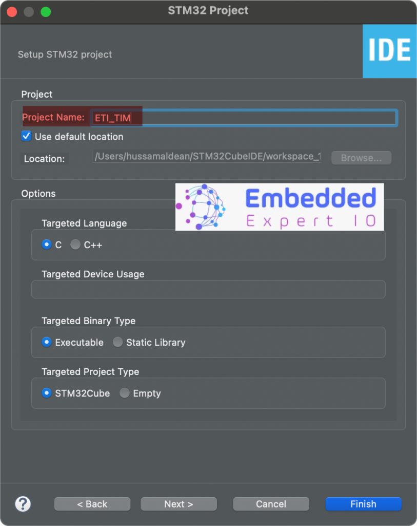
Click on Finish.
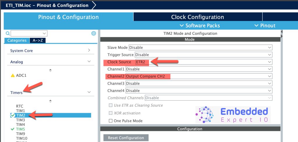
Next, STM32CubeMX window will appear, from timer configure TIM2 as follows:
- Clock Source to ETR2, this will set PA0 as ETR source for TIM2.
- Set Channel2 as Output Compare CH2, this will set PB3 as TIM2_CH2 output.
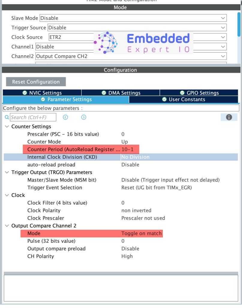
Next, in Parameter Settings, configure the timer as follows:
- Set Counter Period (ARR) to 10-1, this will make the timer counts 10 edges before overflow.
- Output Compare Mode to toggle on match.
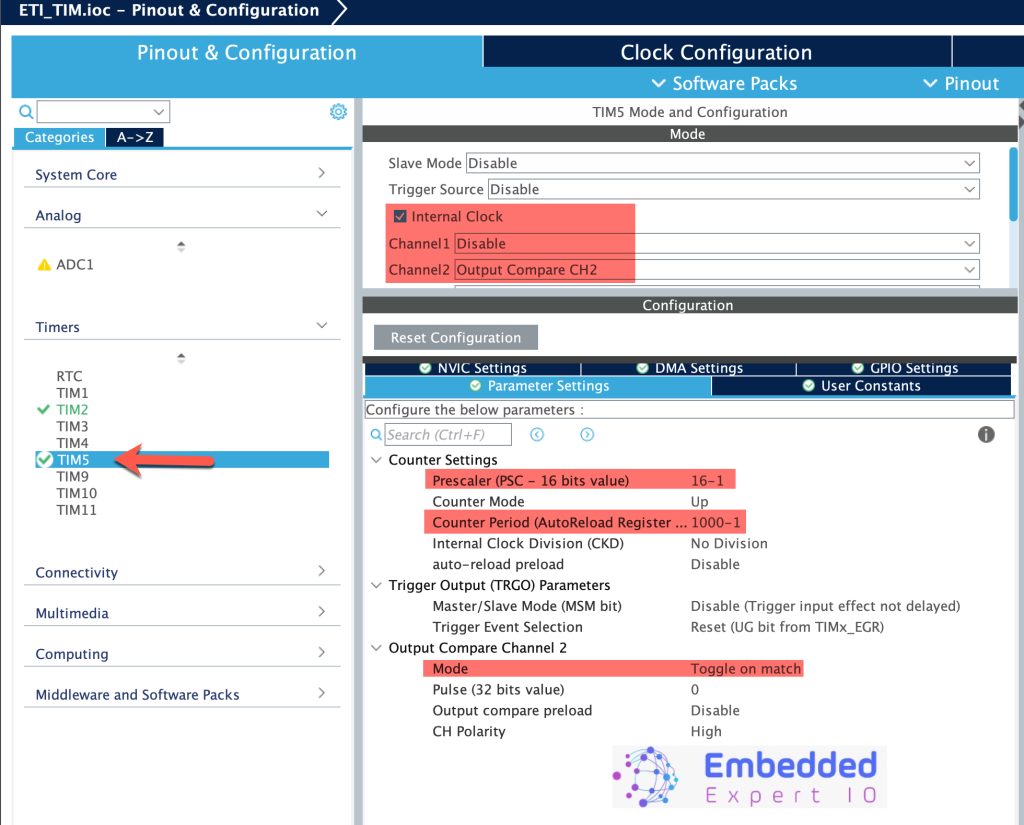
Next, we shall configure TIM5 as follows:
- Check Internal clock.
- Set CH2 as Output Compare, this will set AP2 as TIM5_CH2.
- Set the prescaler to 16-1.
- Set Counter Period to 1000-1, this will give toggle rate of 1KHz (1ms on, 1ms off).
- Set mode to toggle on match.
For more information about output compare, check this guide here.
Thats all for the STM32CubeIDE setup. Save the project and it shall generate the project.
3. Connection:
The connection as follows:
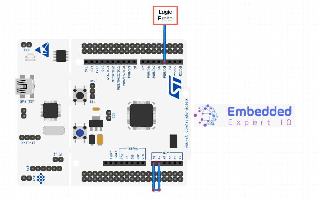
Simply, connect PA0 to PA1 (A0 to A1 of Arduino board) and PB3 (D3 of arduino) to monitor the output of TIM2_CH2.
4. Firmware Developing:
After the project has been generated, main.c shall be opened.
In user code begin 2 in main function, simply start both timers in Output compare mode as follows:
  HAL_TIM_OC_Start(&htim2, TIM_CHANNEL_2);
  HAL_TIM_OC_Start(&htim5, TIM_CHANNEL_2);
Thats all for the guide.
Build the project and start a debugging session as following:

5. Results:
Once you probe TIM2_CH2 and TIM5_CH2 using logic analyzer or oscilloscope, you should get the following:
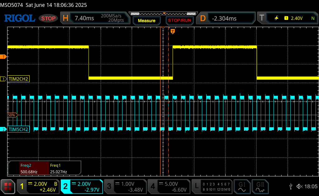
Note that the frequency of TIM5_CH2 is 500Hz as configured in the settings and the output is toggling after the 11th counter which at this point, the timer overflows and timer will toggle the output on CH2. This way, we were able to trigger the TIM2 externally.
Feel free to adapt this code in your next awesome project.
Happy coding 😉
Add Comment