In this first part of our UART guide series, we will explore how to configure UART and send data efficiently.
Mastering these basics is essential before diving into advanced reception and interrupt techniques later.
In this guide, we shall cover the following:
- Introduction to UART.
- STM32CubeIDE setup.
- Firmware Development.
- Results.
1. Introduction to UART:
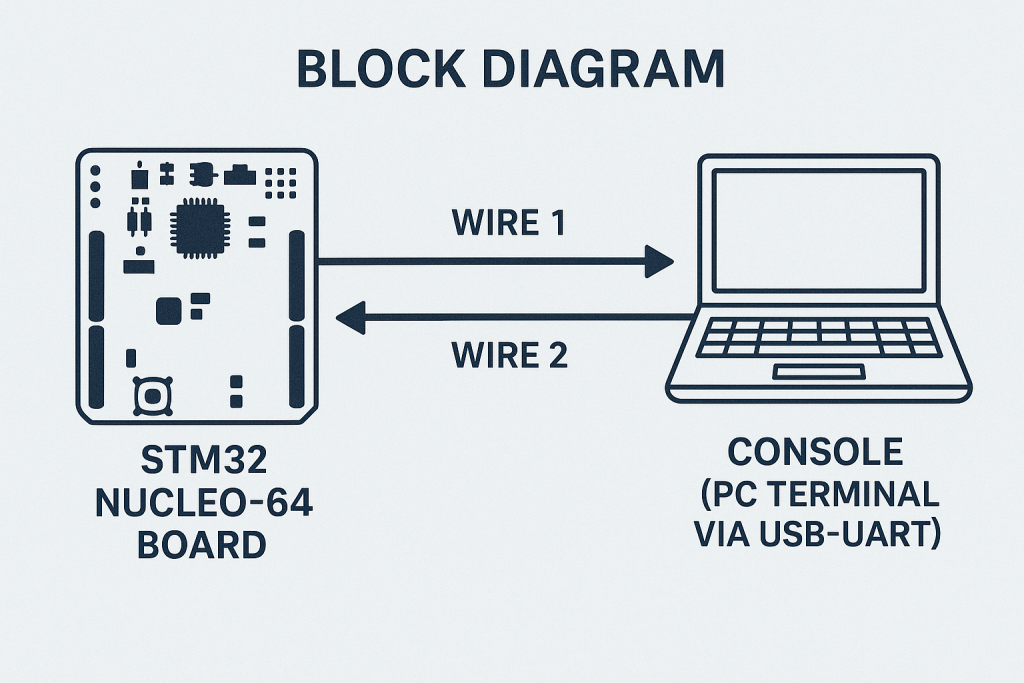
Universal Asynchronous Receiver/Transmitter, commonly known as UART, is one of the most fundamental communication peripherals in embedded systems. It enables serial communication between two devices using only two wires: transmit (TX) and receive (RX). Unlike parallel communication, UART transmits data bits sequentially, reducing pin usage and simplifying PCB routing, making it ideal for interfacing microcontrollers with PCs, sensors, GPS modules, Bluetooth modules, and more.
What is UART?
UART is a hardware communication protocol used for asynchronous serial communication. It converts parallel data from the CPU into serial form for transmission and vice versa for reception. Being asynchronous, UART does not require a separate clock line; instead, it relies on both devices agreeing upon a common baud rate, data bits, parity, and stop bits to frame each transmitted byte correctly. Start and stop bits indicate the beginning and end of each byte frame, ensuring data integrity even without a dedicated clock signal.
Features of UART on STM32
STM32 microcontrollers integrate powerful and flexible UART peripherals with advanced features, including:
- Configurable baud rate up to several Mbps depending on the STM32 series and clock configuration.
- Support for parity control (even, odd, or none) and configurable stop bits.
- Hardware flow control (RTS/CTS) support for robust data transfer, especially at high baud rates.
- DMA support to offload data transfer from the CPU for high-speed communication.
- Interrupt-driven transmission and reception, allowing efficient non-blocking communication.
- Wakeup from Stop mode via UART line activity in low-power applications.
- Some STM32 families integrate LIN, IrDA, or SmartCard modes within the UART peripheral for broader protocol support.
These features make STM32 UART peripherals highly versatile for embedded applications requiring reliable and efficient serial data transfer.
UART vs USART
While often used interchangeably, UART and USART are technically distinct:
| Feature | UART | USART |
|---|---|---|
| Full Name | Universal Asynchronous Receiver/Transmitter | Universal Synchronous/Asynchronous Receiver/Transmitter |
| Communication Mode | Asynchronous only | Supports both synchronous and asynchronous modes |
| Clock Line | No clock line; relies on start/stop bits for framing | Uses a clock line in synchronous mode for data alignment |
| Wiring | Requires only TX and RX wires | Requires TX, RX, and CLK in synchronous mode |
| Speed and Reliability | Generally slower due to no clock synchronization | Faster and more reliable in synchronous mode |
| Common Use Cases | Serial console, GPS, Bluetooth modules, general UART devices | High-speed peripherals requiring synchronization, SPI-like communication, or fallback to UART mode |
| Availability on STM32 | Available as UART peripherals or USART configured in UART mode | Available as USART peripherals with optional sync mode |
2. STM32CubeIDE Setup:
Open STM32CubeIDE after selecting the workspace and create new project as following:

Select the MCU:

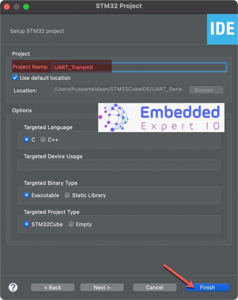
Give the project a name and click on finish:
Next, we need to configure the pins.
Since this guide uses STM32F446RE, it has built in USB-TTL converter over ST-Link.
From the schematic of the board, we can find the pins associated with ST-Link VCP as follows:
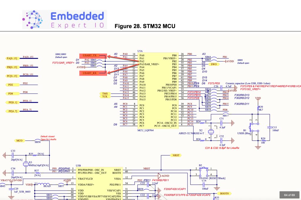
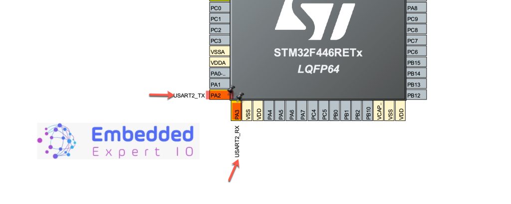
The pins are PA2 and PA3, hence configure these pins as follows:
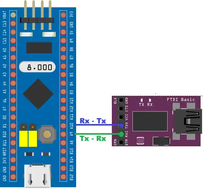
In case you have barebone board like STM32F401 BlackPill, enable UART and the associated pins will be configured and connected external TTL-USB converter as follows:
In this example, UART1 is used and PA9 and PA10 are used for UART.
Next, enable UART2 since the pins are related to UART2 as follows:
Next, UART Configuration:
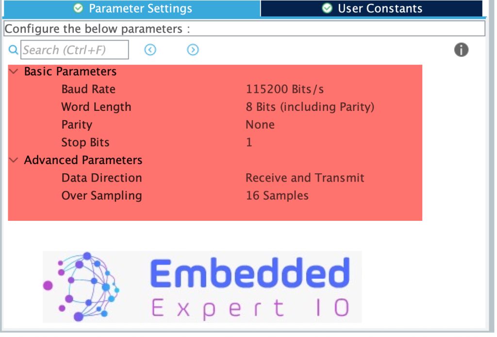
Basic Parameters
Baud Rate: 115200 Bits/s
- Defines the speed of data transmission.
- 115200 bps is a standard high-speed rate for serial consoles.
- Both transmitter and receiver must have matching baud rates for proper communication.
Word Length: 8 Bits (including Parity)
- Specifies the size of data bits in each frame.
- Here, 8 bits per frame are used, which is standard for most applications.
- Note: The phrase “including Parity” indicates the configuration UI is set to show how parity bit would adjust word length, but since parity is None here, it’s simply 8 data bits.
Parity: None
- No parity bit is used for error checking.
- Simplifies communication but does not detect single-bit errors.
- Options are usually None, Even, or Odd.
Stop Bits: 1
- Defines the number of bits sent at the end of each data packet to indicate a stop condition.
- 1 stop bit is the most common setting for standard serial communication.
Advanced Parameters
Data Direction: Receive and Transmit
- Enables the UART peripheral for both sending and receiving data.
- Other possible options are Transmit only or Receive only depending on application needs.
Over Sampling: 16 Samples
- Determines how many times the UART samples each bit period.
- 16x oversampling is standard, providing high noise immunity by sampling each bit 16 times to determine its value reliably.
- Some STM32 UARTs support 8x oversampling for higher baud rates at the cost of reduced noise margin.
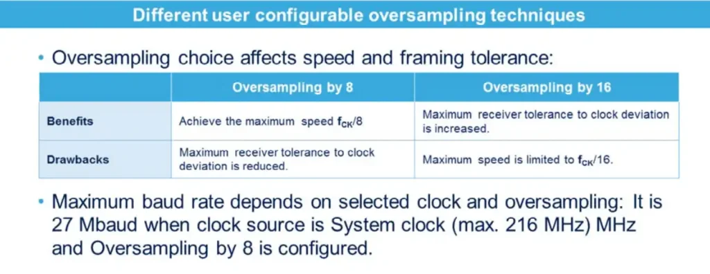
What is Oversampling in UART?
Oversampling is a technique used by the UART peripheral to sample the incoming data line multiple times per bit period. Instead of sampling exactly once at the expected bit center, the UART takes multiple samples and uses them to determine the correct logic level. This greatly improves noise immunity and timing tolerance.
How does it work?
For example, with 16x oversampling:
- The UART samples the RX line 16 times per bit period.
- The receiver determines the majority value or samples at a calculated optimal time to reconstruct the bit.
- This reduces the chance of misreading bits due to noise, jitter, or slight baud rate mismatches between transmitter and receiver.
Oversampling Options on STM32
- 16x oversampling (default)
- Provides better noise immunity.
- Requires the UART clock frequency to be 16 times the baud rate or higher.
- Common for standard communication where reliability is prioritized.
- 8x oversampling (optional)
- Reduces the minimum required UART clock frequency (only 8 times baud rate needed).
- Allows higher baud rates if your peripheral clock frequency is limited.
- Slightly less robust against noise compared to 16x oversampling.
When to use each?
| Oversampling Rate | Advantages | Disadvantages |
|---|---|---|
| 16x | Higher noise immunity; better sampling accuracy | Requires higher peripheral clock frequency |
| 8x | Allows higher baud rates with limited clock speeds | Slightly reduced noise immunity |
Thats all for the configuration. Save the project this will generate the code.
3. Firmware Development:
Once the project has been generated, the main.c file shall be open.
In main.c file , user code begin includes, include stdio libarary as follows:
#include "stdio.h"
Next, in user code begin PV (Private Variables), declare the following variables:
uint8_t uart_data[100]={0};

uint8_t counter=0;- uart_data is a buffer where to hold the data to be transmitted.
- counter to indicate our loop is working and uart is printing.
Next, in user code begin 3 in while 1 loop, add the following:
	  uint16_t len=sprintf(uart_data,"Counter Value = %d\r\n",counter);
	  HAL_UART_Transmit(&huart2, uart_data, len, 100);
	  counter++;
	  HAL_Delay(10);
Line-by-line breakdown
1. uint16_t len = sprintf(uart_data, "Counter Value = %d\r\n", counter);
- Uses
sprintf()to format a string containing the current value ofcounter. uart_datais the character array (buffer) where the formatted string is stored.- The resulting string looks like:
"Counter Value = 123\r\n" sprintf()returns the number of characters written, stored inlen, which will be used as the data length for transmission.
2. HAL_UART_Transmit(&huart2, uart_data, len, 100);
- Calls the STM32 HAL function to transmit data over UART.
&huart2: pointer to the UART handle (here, USART2 peripheral).uart_data: pointer to the data buffer to send.len: number of bytes to transmit (calculated bysprintf).100: timeout in milliseconds to wait for the transmission to complete.
3. counter++;
- Increments the counter variable by 1 for the next loop iteration.
- Each transmission will show an updated counter value.
4. HAL_Delay(10);
- Adds a 10 ms delay before the next transmission.
- Prevents flooding the UART line with data too rapidly.
Thats all for the firmware.
Build the project and run it.
4. Results:
Using your favourite uart terminal and set the baud rate to 115200, you should get the following:
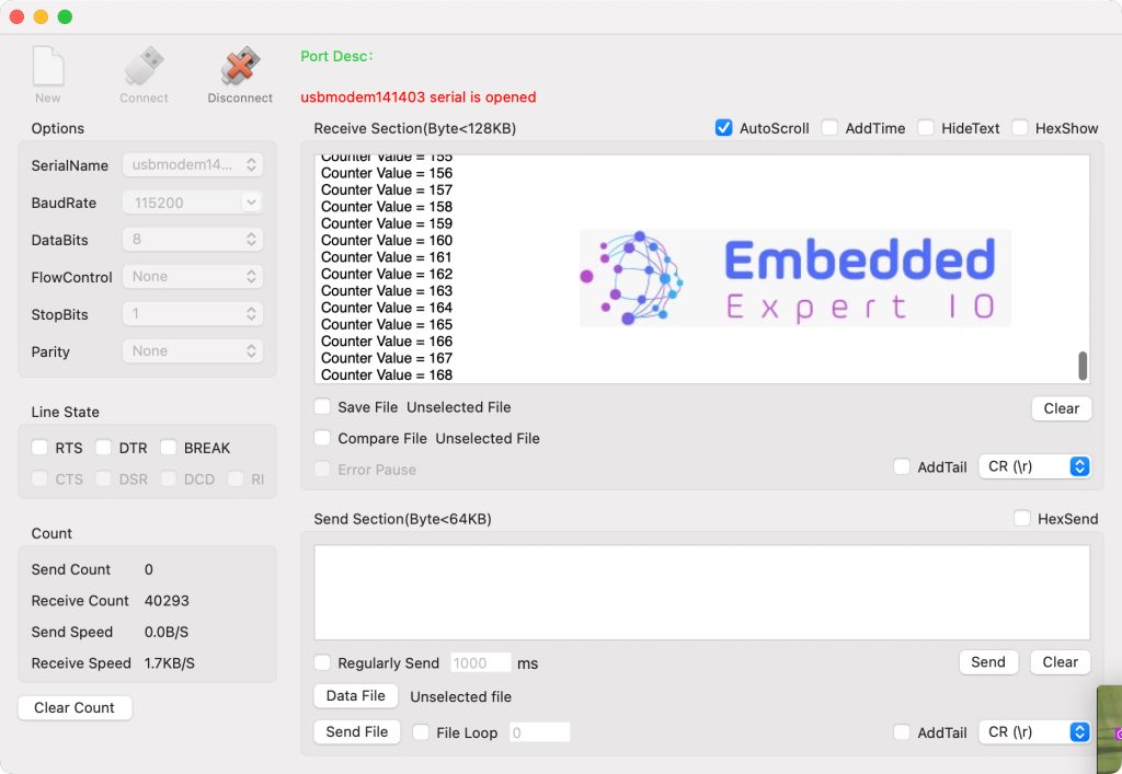
We have successfully transmitted data over the UART and it has variable length and text.
Stay tuned for part 2.
Happy coding 😉
Add Comment