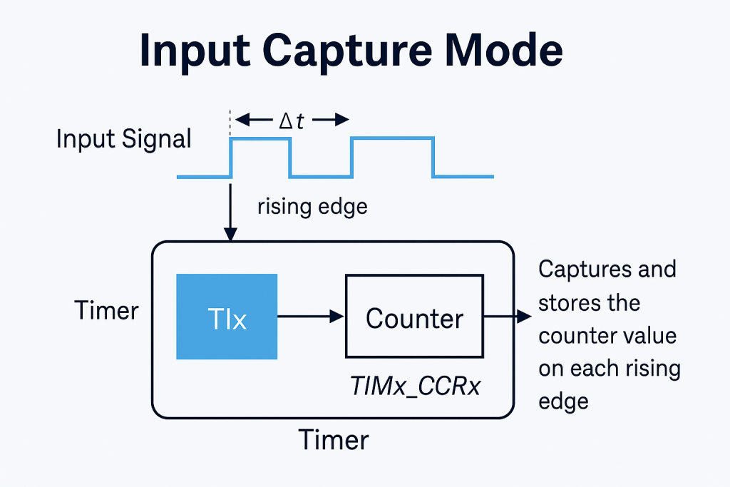
In this guide, we shall use DMA to capture the both, rising and falling edge of a signal. Once they have been captured, we shall use these to measure the frequency and duty cycle of the signal.
In this guide, we shall cover the following:
- STM32CubeMX configuration.
- Firmware development.
- Connection.
- Results.
1. STM32CubeMX Configuration:
We shall continue from the previous guide here.
Open the .ioc file and STM32CubeMX window shall appear.
Once STM32CubeMX appears, we shall configure the clock to maximum as follows:
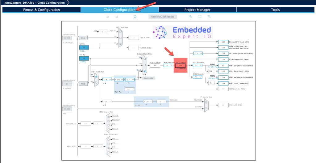
Set the frequency to maximum allowed by your MCU. In this case, 100MHz.
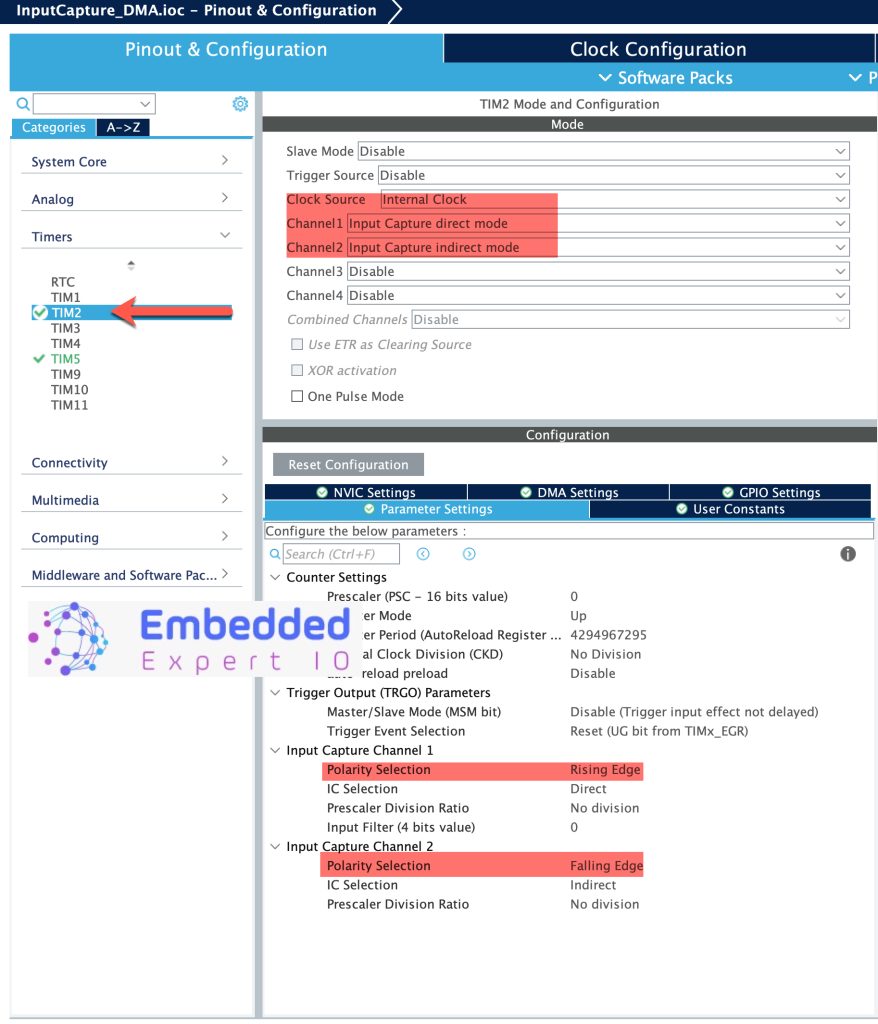
Next, from Pinout and Configuration, configure TIM2 as follows:
- Clock Source to internal Clock.
- Channel1 input capture direct mode.
- Channel2 input capture indirect mode.
Configure Channels as follows:
- Channel1 Polarity to Rising Edge.
- Channel2 Polarity to Falling Edge.
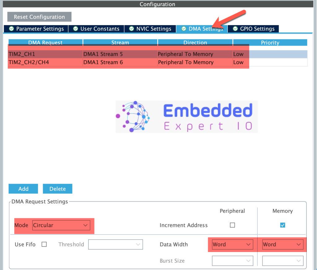
Next, we shall configure the DMA as follows:
- Add DMA handler for TIM2_CH1 and TIM_CH2/CH4 (they are sharing same DMA).
- Set mode to Circular for both.
- Data width for Word.
- Make sure the direction is Peripheral to Memory.
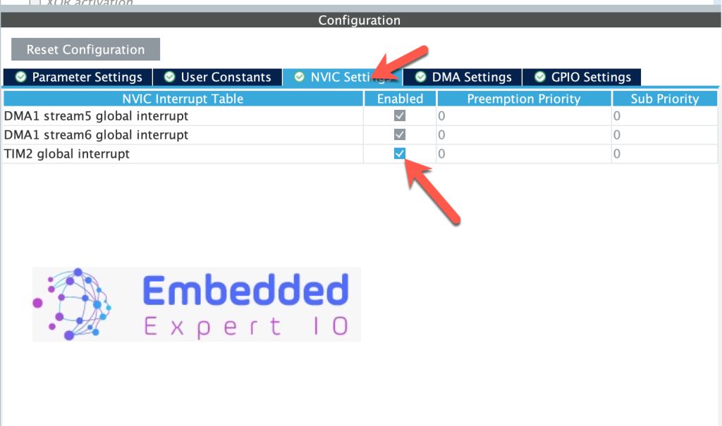
Next, enable TIM2 interrupt as follows:
Next, we shall configure TIM5_CH2 as PWM output as follows:
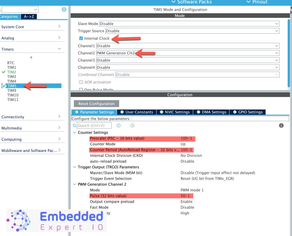
For more details about PWM in timers, please refer to this guide.
Thats all for the guide.
Save the project this will generate the code.
2. Firmware Development:
Once the project has been generated, main.c shall be opened.
In user code begin PV of main.c, declare the following:
long unsigned int IC_Value1 = 0;
long unsigned int IC_Value2 = 0;

long unsigned int period1=0;
long unsigned int period2=0;
float frequency=0;
float duty=0;

volatile long unsigned int previous_IC_Value1=0;
volatile long unsigned int previous_IC_Value2=0;
The IC_Values are for Rising and falling edges respectively.
periods are for rising and falling edges respectively.
Previous_IC_value for Rising and falling edges respectively.
Next, once the timer has captured the edge and DMA moved the data from timer to memory location, the AL_TIM_IC_CaptureCallback shall be called.
The function as follows:
void HAL_TIM_IC_CaptureCallback(TIM_HandleTypeDef *htim)
{
    if (htim->Channel == HAL_TIM_ACTIVE_CHANNEL_1) // Rising edge
    {
        IC_Value1 = HAL_TIM_ReadCapturedValue(htim, TIM_CHANNEL_1);

        if (IC_Value1 >= previous_IC_Value1)
            period1 = IC_Value1 - previous_IC_Value1;
        else
            period1 = (0xFFFFFFFF - previous_IC_Value1 + 1) + IC_Value1;

        previous_IC_Value1 = IC_Value1;

        // Calculate frequency in Hz (timer running at 100 MHz → period in µs)
        frequency = 100000000.0f / period1;
    }

    if (htim->Channel == HAL_TIM_ACTIVE_CHANNEL_2) // Falling edge
    {
        IC_Value2 = HAL_TIM_ReadCapturedValue(htim, TIM_CHANNEL_2);

        if (IC_Value2 >= previous_IC_Value1)
            period2 = IC_Value2 - previous_IC_Value1;  // high time = fall - last rise
        else
            period2 = (0xFFFFFFFF - previous_IC_Value1 + 1) + IC_Value2;

        previous_IC_Value2 = IC_Value2;

        // Optionally, calculate duty cycle
        duty = (float)period2 / period1 * 100.0f;
    }
}
Within the function:
Check the interrupt channel, if it is channel1:
- Get the current captured value.
- Compare the stored previously value with the current and calculate the period and overflow management and calculate the frequency.
If it is channel2:
- Calculate the period in order to calculate the duty cycle as follows:
Duty cycle is measured by capturing the time the signal stays high during one full period of the PWM cycle:
- Rising edge (CH1): Marks the start of the high pulse.
- Falling edge (CH2): Marks the end of the high pulse.
- Next rising edge: Marks the start of the next cycle.
- Formula:
- Duty Cycle=(High TimePeriod)×100%Duty Cycle=(PeriodHigh Time)×100%
- In code:
period1 = time_between_rising_edgesperiod2 = time_from_rising_to_falling_edge (high time)
In user code begin 2 in main function:
  HAL_TIM_IC_Start_DMA(&htim2, TIM_CHANNEL_1,(uint32_t)&IC_Value1,1);
  HAL_TIM_IC_Start_DMA(&htim2, TIM_CHANNEL_2,(uint32_t)&IC_Value2,1);
  HAL_TIM_PWM_Start(&htim5, TIM_CHANNEL_2);
Start both channel in DMA mode.
The function shall take the following:
- Instant to the timer which htim2 in this case.
- Timer channel (TIM_CHANNEL_1 and CHANNEL_2).
- Variable to store the captured value.
- Size of the array which is 1 in this case.
Last start the PWM signal.
Thats all for the guide.
Build the project and start a debugging session as following:

3. Connection:
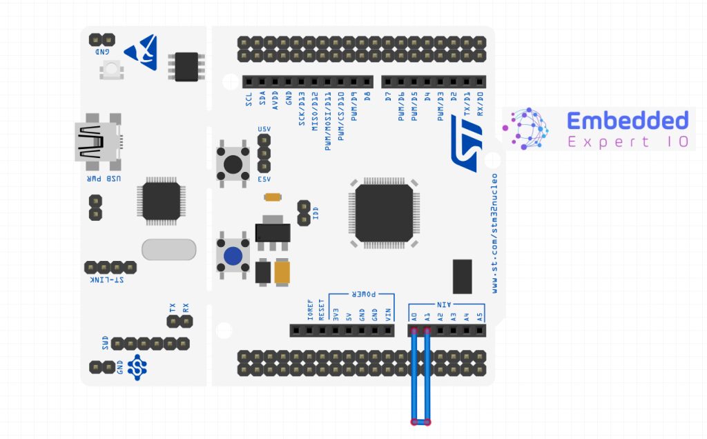
The connection as simple as connecting jumper wires between PA0 and PA1. In case of Nucleo-64 board, connect A0 arduino pin to A1 Arduino pin as shown below:
4. Results:
Add IC_Value1, IC_Value2, period1, period3, duty and frequency to Live Expression.
Run the program and you should get the following:
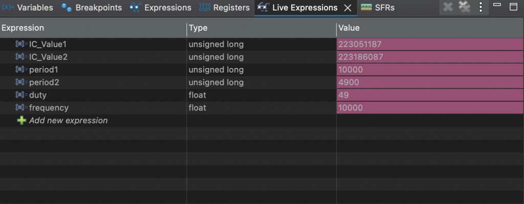
The duty which is 49 as set in the code.
Frequency of 10KHz which is the frequency of the PWM.
In next part, we shall use more efficient method of PWM input to measure the frequency and duty cycle.
Staty tuned.
Happy coding 😉
2 Comments
Why do you use DMA here?
Hi,
this will offload the moving data from interrupt level to hardware level.
DMA will improve the performance by miles.
Add Comment