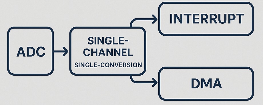
In this second part of the ADC series on STM32, we explore how to handle single-channel, single-conversion ADC using interrupts and DMA. To enhance efficiency and reduce CPU load, these methods enable automatic data handling upon conversion completion, making them ideal for responsive and real-time applications.
In this guide, we shall cover the following:
- Why using interrupt and DMA.
- STM32CubeMX Setup.
- Firmware Development.
- Results.
1. Why Using Interrupt and DMA:
Why Use Interrupts and DMA with ADC on STM32?
In embedded systems, the Analog-to-Digital Converter (ADC) is a crucial peripheral that allows microcontrollers to interact with the analog world—whether it’s monitoring sensor voltages, reading battery levels, or sampling audio signals. While polling is the simplest method to check for conversion completion, it is often inefficient and unsuitable for time-critical or power-sensitive applications. This is where interrupts and Direct Memory Access (DMA) come into play.
The Limitations of Polling
In polling mode, the CPU must constantly check a status flag (typically the End Of Conversion bit) to determine when the ADC has completed a conversion. This approach has several drawbacks:
- Wastes CPU Cycles: The processor is stuck in a loop doing nothing useful while waiting for the conversion to finish.
- Increases Power Consumption: Since the CPU stays active during polling, it consumes more power, which is problematic for battery-powered devices.
- Poor Responsiveness: Polling occupies CPU time that could be used for other tasks, reducing the system’s responsiveness and multitasking capabilities.
- Not Scalable: As the number of ADC channels or sampling frequency increases, polling quickly becomes impractical.
Benefits of Using Interrupts
With interrupt-driven ADC, the microcontroller is notified only when a conversion is complete. This offers several advantages:
- Non-blocking Operation: The CPU can perform other tasks or enter a low-power mode while the ADC is converting.
- Improved Efficiency: The application becomes event-driven, reducing unnecessary CPU usage.
- Real-time Response: Suitable for applications that require immediate action after conversion (e.g., threshold detection, digital control loops).
- Simpler Code Structure: Interrupt service routines (ISRs) allow clean separation between triggering and handling ADC events.
However, in high-speed sampling or continuous conversions, interrupt frequency may become too high, leading to increased context-switching overhead.
Advantages of Using DMA with ADC
DMA (Direct Memory Access) takes efficiency a step further by offloading data transfers from the CPU entirely:
- Automatic Data Transfer: Conversion results are moved directly from the ADC data register to a memory buffer without CPU intervention.
- Ideal for High-Speed Sampling: Perfect for applications such as audio acquisition, waveform analysis, or oscilloscope-like interfaces, where large volumes of data need to be moved rapidly.
- Low CPU Overhead: Frees up the processor to handle only post-processing or higher-level logic, not data movement.
- Supports Circular Buffering: DMA can be configured in circular mode for continuous acquisition and processing, useful in filters or rolling-average calculations.
- Deterministic Timing: Since DMA operations happen in hardware, timing is consistent and not affected by software jitter.
2. STM32CubeIDE Setup:
From the setup of the previous guide from here.
Open.ioc file and STM32CubeMX window shall appear.
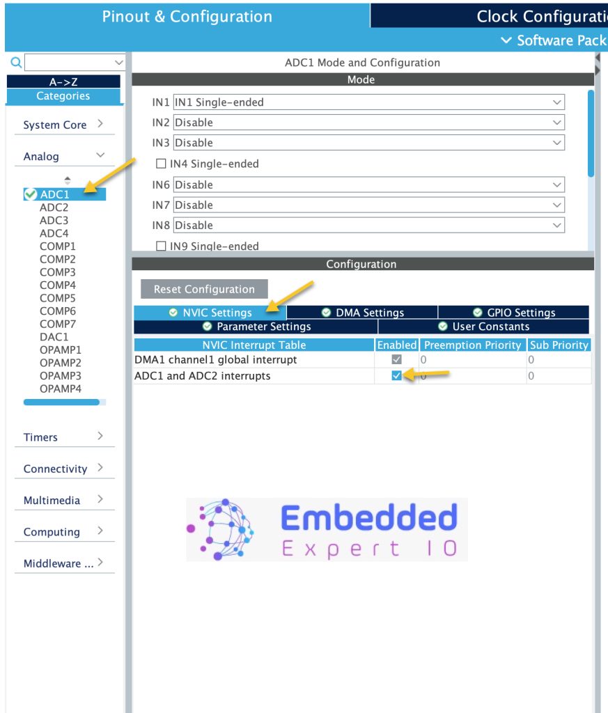
From analog section, select NVIC Setting and enable ADC1 and ADC2 interrupts as following:
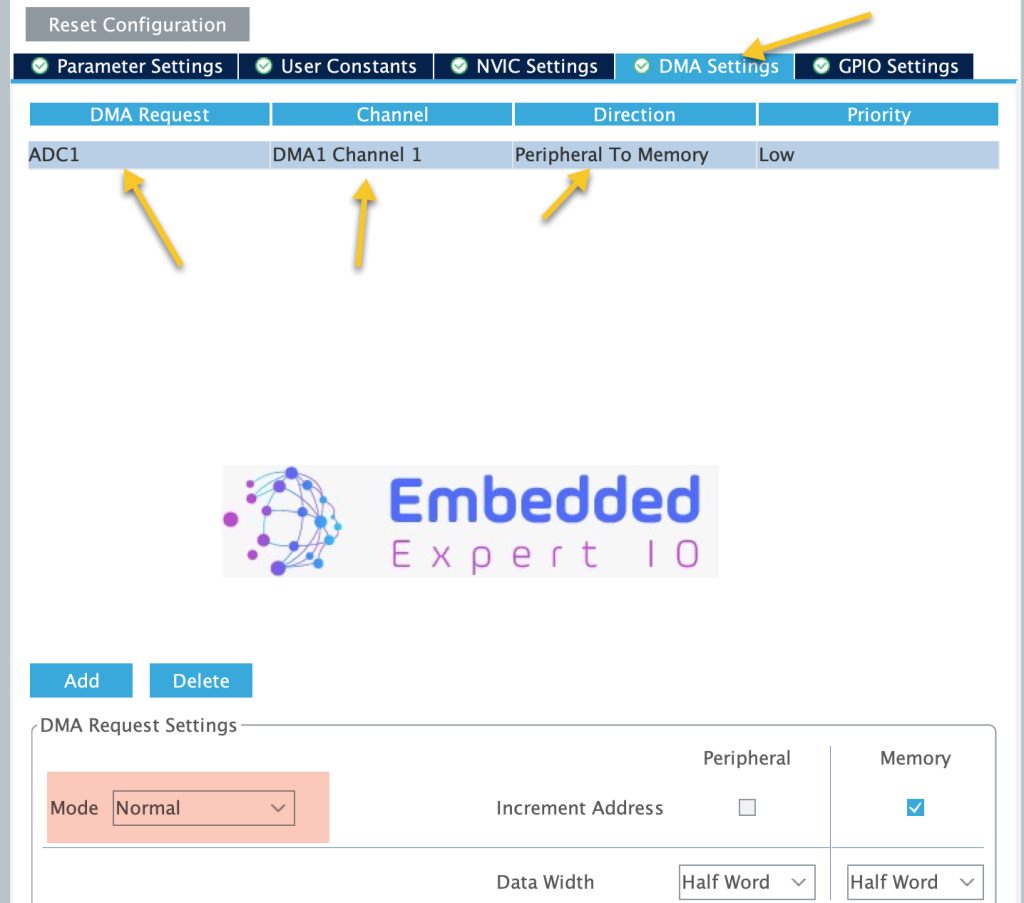
Next, from DMA Settings, enable the DMA as following:
Make sure to set the mode to normal not circular.
Thats all for the configuration. Save the project and it will generate the project.
3. Firmware Development:
Once the project has been generated, main.c shall be opened.
3.1 Interrupt Method:
In user code begin PV declare extra variable to handle the interrupt as following:
volatile uint8_t ADC_Completed=0;
This variable shall set to 1 once the ADC conversion is completed and adcConvCmpltCallback is called
In user code begin 2 in main function, start the adc in interrupt mode as following:
HAL_ADC_Start_IT(&hadc1);
Once the conversion is completed, the HAL_ADC_ConvCpltCallback function shall be called as following:
void HAL_ADC_ConvCpltCallback(ADC_HandleTypeDef* hadc)
{
	if(hadc->Instance==ADC1)
	{
		ADC_Completed=1;

	}

}
Within the callback function, check if the interrupt source is ADC1 or not. If it is, set ADC_Completed to 1.
In while 1 loop:
while(ADC_Completed==0);
ADC_Completed=0;
adcValue = HAL_ADC_GetValue(&hadc1);
HAL_ADC_Start_IT(&hadc1);
Wait until the ADC_Completed is set to 1.
Once it has been set, reset it back to zero, get the ADC value and start the ADC again and loop shall continue like this forever.
3.2 DMA Method:
In user code begin 2 in main function, start the ADC in DMA mode as following:
HAL_ADC_Start_DMA(&hadc1, (uint32_t)&adcValue, 1);
The function shall take the following parameters:
- instant to the ADC which is hadc1 in this case.
- Address of the variable or array to hold the converted data.
- Size of the data which is 1 in this case.
Once the conversion is completed, the HAL_ADC_ConvCpltCallback function shall be called as following:
void HAL_ADC_ConvCpltCallback(ADC_HandleTypeDef* hadc)
{
	if(hadc->Instance==ADC1)
	{
		HAL_ADC_Start_DMA(&hadc1, (uint32_t)&adcValue, 1);
	}

}
Note that in this case, we don’t need to set the variable and only start the ADC in DMA once again.
While loop should be empty.
Thats all for the firmware development.
4. Results:
Start a debug session and add adcValue to live expression
When the pot is near the GND wire, you will get zero or near zero value as following:

On the other size of the pot:

We have successfully created ADC driver that uses either DMA or interrupt to get the data.
Stay tuned where we shall cover the continuous mode in all three cases.
Stay tuned.
Happy coding 😉
Add Comment