In the previous guide (here), we took a look at RS485 and ModBus in general. In the second part, we shall interface MAX485 and develop driver to transmit data.
In this guide, we shall cover the following:
- MAX485.
- Connection.
- Developing driver for MAX485.
4. MAX485:
The signal level used during the RS485 communication method typically ranges from -7V to +12V. The microcontroller pins are generally not designed to handle these levels. This is why these signals needs to be converted to low voltages, for eg ±3V. The module have the MAX485 chip on it, which does most of the job of conversion.
The pinout of the module is shown below
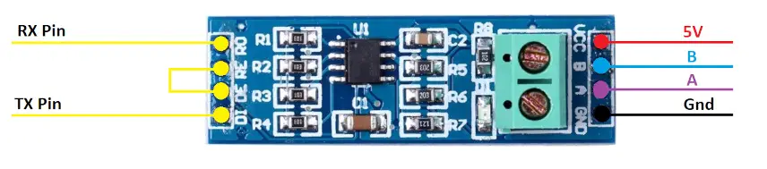
On the left side of the module, the RO pin connects to the RX pin of the UART, and the DI pin connects to the TX pin.
The RE and DE Pins are responsible for setting the module in Receiver or Transmitter mode.
- When the RE pin is LOW and DE pin is LOW, the Module is set in the Receiver mode.
- When the DE pin is HIGH and RE pin is HIGH, the Module is set in the Transmitter mode.
The Pin A and the Pin B are the output pins which carries the transmission signal.
Let’s take an example where we provide the data, 0x95 (10010101) to the module. If the Module is powered with 5V, the output on pins A and B will be as shown below
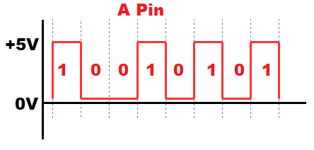
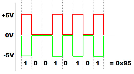
- Since A is the non-inverting pin, it’s output will be in sync to the input. It varies between 0 to +5V
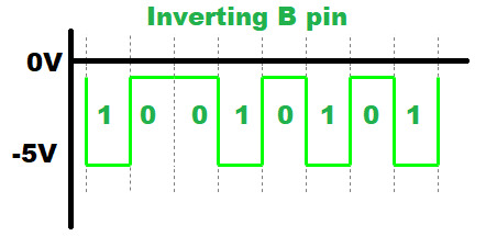
- B is the inverting pin, so the output is inverted and varies between -5V to 0
- When the second module receives these as inputs, it decode the data based on the voltage differences.
- If the voltage difference is maximum, the bit is 1, and if the difference is 0 the bit is 0
- This data is then converted to lower voltages (0 to 3V) to suit the MCU requirement.
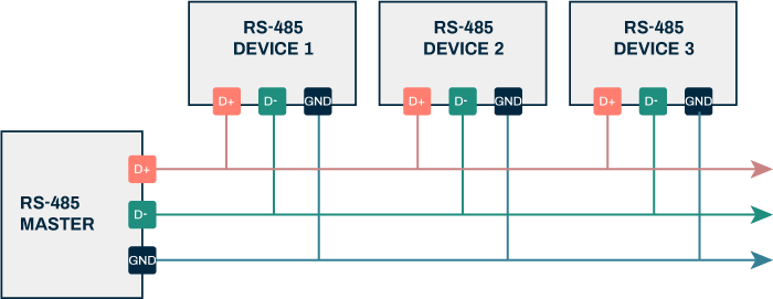
5. Connection:

As shown above, The RO pin is connected to the PA10 (UART1 RX) and DI pin is connected to the PA9 (UART1 TX).
The RE and DE are connected together with the pin PA0, which we have set as the output in the MCU.
6. Developing the Driver:
We start off by creating new source and header file with name of modbus_crc.c and modbus_crc.h respectively.
In the header file:
#ifndef INC_MODBUS_CRC_H_
#define INC_MODBUS_CRC_H_

uint16_t crc16(uint8_t *buffer, uint16_t buffer_length);


#endif /* INC_MODBUS_CRC_H_ */
In the source file:
#include "stdint.h"
#include "modbus_crc.h"
/* Table of CRC values for high-order byte */
static const uint8_t table_crc_hi[] = {
    0x00, 0xC1, 0x81, 0x40, 0x01, 0xC0, 0x80, 0x41, 0x01, 0xC0,
    0x80, 0x41, 0x00, 0xC1, 0x81, 0x40, 0x01, 0xC0, 0x80, 0x41,
    0x00, 0xC1, 0x81, 0x40, 0x00, 0xC1, 0x81, 0x40, 0x01, 0xC0,
    0x80, 0x41, 0x01, 0xC0, 0x80, 0x41, 0x00, 0xC1, 0x81, 0x40,
    0x00, 0xC1, 0x81, 0x40, 0x01, 0xC0, 0x80, 0x41, 0x00, 0xC1,
    0x81, 0x40, 0x01, 0xC0, 0x80, 0x41, 0x01, 0xC0, 0x80, 0x41,
    0x00, 0xC1, 0x81, 0x40, 0x01, 0xC0, 0x80, 0x41, 0x00, 0xC1,
    0x81, 0x40, 0x00, 0xC1, 0x81, 0x40, 0x01, 0xC0, 0x80, 0x41,
    0x00, 0xC1, 0x81, 0x40, 0x01, 0xC0, 0x80, 0x41, 0x01, 0xC0,
    0x80, 0x41, 0x00, 0xC1, 0x81, 0x40, 0x00, 0xC1, 0x81, 0x40,
    0x01, 0xC0, 0x80, 0x41, 0x01, 0xC0, 0x80, 0x41, 0x00, 0xC1,
    0x81, 0x40, 0x01, 0xC0, 0x80, 0x41, 0x00, 0xC1, 0x81, 0x40,
    0x00, 0xC1, 0x81, 0x40, 0x01, 0xC0, 0x80, 0x41, 0x01, 0xC0,
    0x80, 0x41, 0x00, 0xC1, 0x81, 0x40, 0x00, 0xC1, 0x81, 0x40,
    0x01, 0xC0, 0x80, 0x41, 0x00, 0xC1, 0x81, 0x40, 0x01, 0xC0,
    0x80, 0x41, 0x01, 0xC0, 0x80, 0x41, 0x00, 0xC1, 0x81, 0x40,
    0x00, 0xC1, 0x81, 0x40, 0x01, 0xC0, 0x80, 0x41, 0x01, 0xC0,
    0x80, 0x41, 0x00, 0xC1, 0x81, 0x40, 0x01, 0xC0, 0x80, 0x41,
    0x00, 0xC1, 0x81, 0x40, 0x00, 0xC1, 0x81, 0x40, 0x01, 0xC0,
    0x80, 0x41, 0x00, 0xC1, 0x81, 0x40, 0x01, 0xC0, 0x80, 0x41,
    0x01, 0xC0, 0x80, 0x41, 0x00, 0xC1, 0x81, 0x40, 0x01, 0xC0,
    0x80, 0x41, 0x00, 0xC1, 0x81, 0x40, 0x00, 0xC1, 0x81, 0x40,
    0x01, 0xC0, 0x80, 0x41, 0x01, 0xC0, 0x80, 0x41, 0x00, 0xC1,
    0x81, 0x40, 0x00, 0xC1, 0x81, 0x40, 0x01, 0xC0, 0x80, 0x41,
    0x00, 0xC1, 0x81, 0x40, 0x01, 0xC0, 0x80, 0x41, 0x01, 0xC0,
    0x80, 0x41, 0x00, 0xC1, 0x81, 0x40
};

/* Table of CRC values for low-order byte */
static const uint8_t table_crc_lo[] = {
    0x00, 0xC0, 0xC1, 0x01, 0xC3, 0x03, 0x02, 0xC2, 0xC6, 0x06,
    0x07, 0xC7, 0x05, 0xC5, 0xC4, 0x04, 0xCC, 0x0C, 0x0D, 0xCD,
    0x0F, 0xCF, 0xCE, 0x0E, 0x0A, 0xCA, 0xCB, 0x0B, 0xC9, 0x09,
    0x08, 0xC8, 0xD8, 0x18, 0x19, 0xD9, 0x1B, 0xDB, 0xDA, 0x1A,
    0x1E, 0xDE, 0xDF, 0x1F, 0xDD, 0x1D, 0x1C, 0xDC, 0x14, 0xD4,
    0xD5, 0x15, 0xD7, 0x17, 0x16, 0xD6, 0xD2, 0x12, 0x13, 0xD3,
    0x11, 0xD1, 0xD0, 0x10, 0xF0, 0x30, 0x31, 0xF1, 0x33, 0xF3,
    0xF2, 0x32, 0x36, 0xF6, 0xF7, 0x37, 0xF5, 0x35, 0x34, 0xF4,
    0x3C, 0xFC, 0xFD, 0x3D, 0xFF, 0x3F, 0x3E, 0xFE, 0xFA, 0x3A,
    0x3B, 0xFB, 0x39, 0xF9, 0xF8, 0x38, 0x28, 0xE8, 0xE9, 0x29,
    0xEB, 0x2B, 0x2A, 0xEA, 0xEE, 0x2E, 0x2F, 0xEF, 0x2D, 0xED,
    0xEC, 0x2C, 0xE4, 0x24, 0x25, 0xE5, 0x27, 0xE7, 0xE6, 0x26,
    0x22, 0xE2, 0xE3, 0x23, 0xE1, 0x21, 0x20, 0xE0, 0xA0, 0x60,
    0x61, 0xA1, 0x63, 0xA3, 0xA2, 0x62, 0x66, 0xA6, 0xA7, 0x67,
    0xA5, 0x65, 0x64, 0xA4, 0x6C, 0xAC, 0xAD, 0x6D, 0xAF, 0x6F,
    0x6E, 0xAE, 0xAA, 0x6A, 0x6B, 0xAB, 0x69, 0xA9, 0xA8, 0x68,
    0x78, 0xB8, 0xB9, 0x79, 0xBB, 0x7B, 0x7A, 0xBA, 0xBE, 0x7E,
    0x7F, 0xBF, 0x7D, 0xBD, 0xBC, 0x7C, 0xB4, 0x74, 0x75, 0xB5,
    0x77, 0xB7, 0xB6, 0x76, 0x72, 0xB2, 0xB3, 0x73, 0xB1, 0x71,
    0x70, 0xB0, 0x50, 0x90, 0x91, 0x51, 0x93, 0x53, 0x52, 0x92,
    0x96, 0x56, 0x57, 0x97, 0x55, 0x95, 0x94, 0x54, 0x9C, 0x5C,
    0x5D, 0x9D, 0x5F, 0x9F, 0x9E, 0x5E, 0x5A, 0x9A, 0x9B, 0x5B,
    0x99, 0x59, 0x58, 0x98, 0x88, 0x48, 0x49, 0x89, 0x4B, 0x8B,
    0x8A, 0x4A, 0x4E, 0x8E, 0x8F, 0x4F, 0x8D, 0x4D, 0x4C, 0x8C,
    0x44, 0x84, 0x85, 0x45, 0x87, 0x47, 0x46, 0x86, 0x82, 0x42,
    0x43, 0x83, 0x41, 0x81, 0x80, 0x40
};

uint16_t crc16(uint8_t *buffer, uint16_t buffer_length)
{
    uint8_t crc_hi = 0xFF; /* high CRC byte initialized */
    uint8_t crc_lo = 0xFF; /* low CRC byte initialized */
    unsigned int i; /* will index into CRC lookup */

    /* pass through message buffer */
    while (buffer_length--) {
        i = crc_lo ^ *buffer++; /* calculate the CRC  */
        crc_lo = crc_hi ^ table_crc_hi[i];
        crc_hi = table_crc_lo[i];
    }

    return (crc_hi << 8 | crc_lo);
}
This is taken from modbus documentation.
Now, create new source and header file with name of MAX485.c and MAX485.h respectively.
Within the header file:
Start by including the header guard as following:
#ifndef MAX485_H_
#define MAX485_H_


#endif /* MAX485_H_ */
Within the header guard, include stdint library as following:
#include "stdint.h"
Declare the following enum to handle switching between transmission and reception as following:
typedef enum
{
	Receiver =0,
	Transmiter=1
}RS485State;
Declare the following functions:
void MAX485_RE_DE_Init(void);
void SetRS485Mode(RS485State state);
void RS485SendData(uint8_t addr, uint8_t FunCode, uint16_t MemAddr, uint16_t size );
Hence, the header file as following:
#ifndef MAX485_H_
#define MAX485_H_

#include "stdint.h"

typedef enum
{
	Receiver =0,
	Transmiter=1
}RS485State;


void MAX485_RE_DE_Init(void);
void SetRS485Mode(RS485State state);
void RS485SendData(uint8_t addr, uint8_t FunCode, uint16_t MemAddr, uint16_t size );

#endif /* MAX485_H_ */
In the source file, we start by including the MAX485 header file as following:
#include "MAX485.h"
Also, include the STM32F4 main header file:
#include "stm32f4xx.h"
Include both crc and uart header file:
#include "modbus_crc.h"
#include "uart1.h"
We start by configuring the PA0 to handle the change between transmission and reception as following:
void MAX485_RE_DE_Init(void)
{
	RCC->AHB1ENR|=RCC_AHB1ENR_GPIOAEN;

	GPIOA->MODER|=GPIO_MODER_MODE0_0;
	GPIOA->MODER&=~GPIO_MODER_MODE0_1;
}
To change the mode function:
void SetRS485Mode(RS485State state)
{
	switch (state)
	{
	 case Receiver: GPIOA->BSRR=GPIO_BSRR_BR0; break;
	 case Transmiter: GPIOA->BSRR=GPIO_BSRR_BS0; break;
	 default: GPIOA->BSRR=GPIO_BSRR_BR0; break;
	}
}
The function shall take RS485State as argument. Then the function set the pin low if the mode is reception or high if transmission. In case incorrect parameter has been passed, the function shall set MAX485 in reception mode.
Now for transmission the data:
When the master request to read data, the data frame as following:
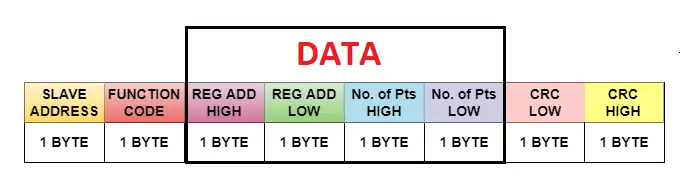
First byte is the address of the slave device.
Function code for read/write.
Register address high and low.
Number of the data to be read.
CRC value.
Hence the transmission function as following:
void RS485SendData(uint8_t addr, uint8_t FunCode, uint16_t MemAddr, uint16_t size )
{
	uint8_t data[8]={0};
	data[0]=addr;
	data[1]=FunCode;
	data[2]=((MemAddr>>8)&0xFF);
	data[3]=((MemAddr)&0xFF);
	data[4]=((size>>8)&0xFF);
	data[5]=((size)&0xFF);
	uint16_t tmp_crc=crc16(data,6);
	data[6]=tmp_crc&0xFF;
	data[7]=(tmp_crc>>8)&0xFF;
	SetRS485Mode(Transmiter);
	UART1_TX(data, 8);
	SetRS485Mode(Receiver);

}
First, declare buffer to hold the data to be transmitted as following:
uint8_t data[8]={0};First byte for the address:
data[0]=addr;
Function code:
data[1]=FunCode;
Memory address:
data[2]=((MemAddr>>8)&0xFF);
data[3]=((MemAddr)&0xFF);
Size of the data:
data[4]=((size>>8)&0xFF);
data[5]=((size)&0xFF);
Last two bytes for the CRC as following:
uint16_t tmp_crc=crc16(data,6);
data[6]=tmp_crc&0xFF;
data[7]=(tmp_crc>>8)&0xFF;
Set the module into transmission mode:
SetRS485Mode(Transmiter);
Send the data:
UART1_TX(data, 8);
Put it back to reception mode:
SetRS485Mode(Receiver);
Hence, the source code as following:
#include "MAX485.h"
#include "stm32f4xx.h"
#include "modbus_crc.h"
#include "uart1.h"


void MAX485_RE_DE_Init(void)
{
	RCC->AHB1ENR|=RCC_AHB1ENR_GPIOAEN;

	GPIOA->MODER|=GPIO_MODER_MODE0_0;
	GPIOA->MODER&=~GPIO_MODER_MODE0_1;
}


void SetRS485Mode(RS485State state)
{
	switch (state)
	{
	 case Receiver: GPIOA->BSRR=GPIO_BSRR_BR0; break;
	 case Transmiter: GPIOA->BSRR=GPIO_BSRR_BS0; break;
	 default: GPIOA->BSRR=GPIO_BSRR_BR0; break;
	}
}

void RS485SendData(uint8_t addr, uint8_t FunCode, uint16_t MemAddr, uint16_t size )
{
	uint8_t data[8]={0};
	data[0]=addr;
	data[1]=FunCode;
	data[2]=((MemAddr>>8)&0xFF);
	data[3]=((MemAddr)&0xFF);
	data[4]=((size>>8)&0xFF);
	data[5]=((size)&0xFF);
	uint16_t tmp_crc=crc16(data,6);
	data[6]=tmp_crc&0xFF;
	data[7]=(tmp_crc>>8)&0xFF;
	SetRS485Mode(Transmiter);
	UART1_TX(data, 8);
	SetRS485Mode(Receiver);

}
In part 3, we shall start communicating with RS485 ModBus enabled device.
Stay tuned.
Happy coding 😉
Add Comment