In this guide series, we shall take a look at RS-485 and Modbus-RTU and develop driver to communicate with RS-485 enabled device.
In this guide, we shall cover the following:
- What is RS-485.
- What is Modbus-RTU.
- Environment Setup.
1. What is RS-485:
RS-485, also known as TIA-485 or EIA-485, is a standard introduced in 1983. It defines the electrical characteristics of drivers and receivers for use in serial communication systems. Here are some key points about RS-485:
- Balanced Signaling: RS-485 uses balanced electrical signaling over twisted pair cables. This makes it robust against noise and interference, making it suitable for industrial environments.
- Multipoint Communication: RS-485 supports multipoint systems, allowing multiple devices to communicate over long distances using a single twisted pair of wires. It’s commonly used in industrial control systems.
- Data Rates and Distances: RS-485 can handle data rates up to 10 Mbit/s (or lower speeds) and distances up to 1,200 meters (4,000 feet).
- Three-State Logic: Unlike RS-422, RS-485 drivers use three-state logic, allowing individual transmitters to be deactivated. This enables linear bus topologies using only two wires.
Remember, RS-485 is a reliable choice for connecting devices in noisy environments or over extended distances.
RS485 is used in many computer and automation systems. Some of the examples are robotics, base stations, motor drives, video surveillance and also home appliances. In computer systems, RS485 is used for data transmission between the controller and a disk drive. Commercial aircraft cabins also use RS485 for low-speed data communications. This is due to the minimal wiring required due to the wiring configuration requirements of RS485.
RS485 is however most popularly used in programmable logic controllers and factory floors where there are lots of electrical noise. RS485 is used as the physical layer for many standards and proprietary automation protocols to implement control systems, most commonly Modbus.
Modbus is the world’s most popular automation protocol in the market. Developed by Modicon, Modbus enables different devices from different manufacturers to be integrated into the main system. Most Modbus implementations use RS485 due to the allowance of longer distances, higher speeds and multiple devices on a single network.
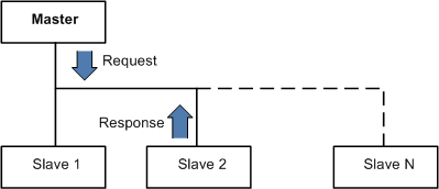
Modbus devices communicate using a Master-Slave technique where only one device (the Master) can initiate transactions (AKA queries). The other devices (the slaves) respond by giving the requested data to the master, or by taking the action requested in the query. This whole system allows manufacturing facilities to control their devices remotely and also set-up automation.
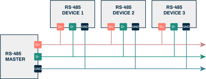
How RS485 works?

Ref: lammertbies
In RS485 standard, data is transmitted via two wires twisted together also referred to as “Twisted Pair Cable”. The twisted pairs in RS485 give immunity against electrical noise, making RS485 viable in electrically noisy environments.
RS485 at its core with 2 wires allows half-duplex data transmission. This means data can be transmitted in both directions to and fro devices one direction at a time. By adding another 2 wires, making it a 4 wires system, it allows data transmission in both directions to and fro devices at the same time, also known as full-duplex. However, in a full-duplex setup, they are limited to a master and slave communication where slaves cannot communicate with each other.
2. What is Modbus-RTU:
Modbus RTU is an open serial protocol derived from the master/slave architecture (now client/server) originally developed by Modicon (now Schneider Electric). It is a widely accepted serial level protocol due to its ease of use and reliability. Modbus RTU is widely used within Building Management Systems (BMS) and Industrial Automation Systems (IAS).
Modbus RTU messages are a simple 16-bit structure with a Cyclic-Redundant Checksum. The simplicity of these messages ensures reliability. Due to this simplicity, the basic 16-bit Modbus RTU register structure can be used to pack in floating point, tables, ASCII text, queues, and other unrelated data.
This protocol primarily uses an RS-232 or RS-485 serial interfaces for communications and is supported by every commercial SCADA, HMI, OPC server and data acquisition software program in the marketplace. This makes it very easy to integrate Modbus-compatible equipment into new or existing monitoring and control applications.
Modbus Communication

The RTU version uses a client/server technique to communicate between devices. Meaning, any application that utilizes the RTU protocol will have a client and at least one server. A client is typically a host supervisory computer running software that will communicate with one or more server devices.
Modbus enables client/server communication between devices connected through buses or networks. On the OSI Model, Modbus is positioned at Level 7. It is intended to be a request/reply protocol and delivers services specified by function codes. The function codes of the protocol are elements of its request/reply Protocol Data Unit.
In order to build the Modbus application data unit, the client must initiate a Modbus transaction. It is the function that informs the server as to which type of action to perform. The format of a request initiated by a client is established by the application protocol. The function code field is then coded into one byte. Only codes within the range of 1 through 255 are considered valid, with 128-255 being reserved for exception responses. When the client sends a message to the server, it is the function code field that informs the server of what type of action to perform.
To define multiple actions, some functions will have sub-function codes added to them. For instance, the client can read the On/Off states of a group of discreet outputs or inputs. It could also read/write the data contents of a group of registers. When the client receives the server response, the function code field is used by the server to indicate either an error-free response or an exception response. The server echoes to the request of the initial function code in the case of a normal response.
Modbus RTU Data Representation

Like everything else about Modbus, the data representation is simple. In fact, data is represented more simply in Modbus than in any other industrial protocol you’ll ever find. The bit of least importance is sent and received first. All devices within the network must interpret each transmitted byte analogously in this manner.
There are no methods for automated recognition of baud rates. The same baud rate must be utilized by the server(s) and client connected to the bus. No specific baud rate is specified by the protocol: typical baud rates are 9600 or 19200.
There are only two data types in Modbus: coils and registers. Coils are simply single bits. The bits can be ON (1) or they can be OFF (0). Some coils represent inputs, meaning they contain the status of some physical discrete input. Or they represent outputs, meaning that they hold the state of some physical discrete output signal. Registers are simply 16-bit unsigned register data. Registers can have a value from 0 to 65535 (0 to FFFF hexadecimal). There is no representation for negative values, no representation for values greater than 65535 and no representation for real data like 200.125.
Registers are grouped into Input Registers and Holding Registers. Like Input Coils, Input Registers report the state of some external input as a value between 0 and 65535. The original intent of an Input Register was to reflect the value of some analog input. It is a digital representation of an analog signal like a voltage or a current. Most Modbus devices today are not I/O devices and Input Registers simply function identically to Holding Registers.
Holding Registers were originally designed as temporary program storage for devices like controllers. Today, Holding Registers function as data storage for devices.
Modbus RTU packets are only intended to send data; they do not have the capability to send parameters such as point name, resolution, units, etc. If the ability to send such parameters is needed, one should investigate a BACnet, EtherNet/IP or other modern protocols.
3. Environment Setup:
Before we start with the environment setup, we need to setup STM32CubeMX in certain way that allow us to develop the firmware using only register. Form more details how to setup STM32CubeIDE, please refer to this guide.
We start off by creating new source and header file with name of delay.c and delay.h
Within the header file:
#ifndef DELAY_H_
#define DELAY_H_

#include "stdint.h"

void Delay_Init(uint32_t freq);
uint64_t millis();
void delay(uint32_t time);

#endif /* DELAY_H_ */
Within the source file:
#include "delay.h"
#include "stm32f4xx.h"


#define	CTRL_ENABLE					(1U<<0)
#define CTRL_CLKSRC					(1U<<2)
#define CTRL_COUNTFLAG				(1U<<16)
#define CTRL_TICKINT				(1U<<1)


volatile uint64_t mil;

void Delay_Init(uint32_t freq)
{

	SysTick->LOAD  = (freq/1000) - 1;

	/*Clear systick current value register */
	SysTick->VAL = 0;

	/*Enable systick and select internal clk src*/
	SysTick->CTRL = CTRL_ENABLE | CTRL_CLKSRC ;

	/*Enable systick interrupt*/
	SysTick->CTRL  |= CTRL_TICKINT;

}


uint64_t Millis()
	{
	__disable_irq();
	uint64_t ml=mil;
	__enable_irq();
	return ml;
	}


void Delay(uint32_t time)
{

	uint64_t start=millis();
	while((millis() - start) < (time+1));
}

void SysTick_Handler(void)
{


	mil++;
}
For detailed how to develop this driver, please refer to this guide.
Next, create new source and header file with name of uart1.c and uart.h respectively.
The UART shall use IDLE Line interrupt with DMA to handle the received data and polling mode to transmit the data.
For more information for how to develop the driver, please refer to this guide.
In the header file:
#ifndef UART1_H_
#define UART1_H_

#include "stdint.h"

void UART1_Pins_Init(void);
void UART1_Init(void);
void UART1_DMA_RX_Until_IDLE(uint8_t *data, uint16_t len);
void UART1_TX(uint8_t *data, uint8_t len);


#endif /* UART1_H_ */
In the source file:
#include "uart1.h"
#include "stm32f4xx.h"


void UART1_Pins_Init(void)
{
	/*Macro for the AF of UART1*/
	#define UART1_AF	0x07

	/*Enable clock access to GPIOA*/
	RCC->AHB1ENR|=RCC_AHB1ENR_GPIOAEN;

	/*Set PA9 and PA10 to alternate */
	GPIOA->MODER|=GPIO_MODER_MODE9_1|GPIO_MODER_MODE10_1;
	GPIOA->MODER&=~(GPIO_MODER_MODE9_0|GPIO_MODER_MODE10_0);

	/*Select which alternate function*/
	GPIOA->AFR[1]|=(UART1_AF<<GPIO_AFRH_AFSEL9_Pos)|(UART1_AF<<GPIO_AFRH_AFSEL10_Pos);

}


void UART1_Init(void)
{
	#define USART1_CH 0x04
	/*UART Configuration*/
	RCC->APB2ENR|=RCC_APB2ENR_USART1EN;

	USART1->BRR  = 0x0681;    //9600 @16MHz
	USART1->CR1|=USART_CR1_TE|USART_CR1_RE;

	USART1->CR1|=USART_CR1_IDLEIE;

	USART1->CR3|=USART_CR3_DMAR;

	NVIC_EnableIRQ(USART1_IRQn);
	USART1->CR1|=USART_CR1_UE;

	/*DMA configuration*/
	RCC->AHB1ENR|=RCC_AHB1ENR_DMA2EN;

	DMA2_Stream2->CR &=~DMA_SxCR_EN;
	while (DMA2_Stream2->CR & DMA_SxCR_EN) {}

	DMA2->LIFCR|=DMA_LIFCR_CDMEIF2|DMA_LIFCR_CFEIF2|DMA_LIFCR_CTCIF2|DMA_LIFCR_CHTIF2|DMA_LIFCR_CTCIF2;

	DMA2_Stream2->CR|=(USART1_CH<<DMA_SxCR_CHSEL_Pos)|(DMA_SxCR_MINC);
}

void UART1_DMA_RX_Until_IDLE(uint8_t *data, uint16_t len)
{
	DMA2_Stream2->M0AR=(uint32_t)data;
	DMA2_Stream2->PAR=USART1->DR;
	DMA2_Stream2->NDTR=len;
    DMA2->LIFCR|=DMA_LIFCR_CDMEIF2|DMA_LIFCR_CFEIF2|DMA_LIFCR_CTCIF2|DMA_LIFCR_CHTIF2|DMA_LIFCR_CTCIF2;
    DMA2_Stream2->CR|=DMA_SxCR_EN;
}


void UART1_TX(uint8_t *data, uint8_t len)
{
	for (int i=0;i<len;i++)
	{
		/*Make sure the transmit data register is empty*/
		while(!(USART1->SR & USART_SR_TXE)){}

		/*Write to transmit data register*/
		USART1->DR	=  (data[i] & 0xFF);
	}
  	while(!(USART1->SR & USART_SR_TC));
	(void)USART1->DR;
}


__WEAK void UART_RX_Complete(void)
{

}

void USART1_IRQHandler(void)
{
	if (USART1->SR & USART_SR_IDLE)
	{

		UART_RX_Complete();
		(void)USART1->DR;
		DMA2_Stream2->CR &= ~DMA_SxCR_EN;         /* disable DMA1 Stream 5 */
		while (DMA2_Stream2->CR & DMA_SxCR_EN) {} /* wait until DMA1 Stream 5 is disabled */

	}

}
In part 2, we shall connect MAX485 TTL UART to RS485 Converter Module with our STM32 and continue developing the driver further.
Stay tuned.
Happy coding 😉
Add Comment