In pervious guides(here), we took look how to receive 5 characters from DMA and echo back the sent characters. However, the limitation is to need the number of received character in advanced which will limit the capability of the firmware utilitized the driver. In this guide, we shall see how configure the UART to detect idle line and generate interrupt to indicate the the last character is received.
In this guide, we shall cover the following:
- What is IDLE line detection.
- IDLE line configuration.
- DMA configuration.
- Code.
- Demo.
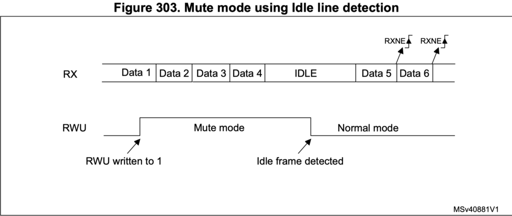
1. What is IDLE line detection:
IDLE line event is triggered if UART RX line is inactive for one frame. The frame time depends on the baudrate. Higher baudrate, lower frame.
2. IDLE Line configuration:
We start of by enabling clock access to Port A and USART2 and configure PA2 and PA3 to work in USART mode:
*Enable clock access to GPIOA and USART2*/
	RCC->APB1ENR|=RCC_APB1ENR_USART2EN;
	RCC->AHB1ENR|=RCC_AHB1ENR_GPIOAEN;
	/*Configure the GPIO for UART Mode*/
	GPIOA->MODER|=GPIO_MODER_MODE2_1;//set bit5
	GPIOA->MODER&=~GPIO_MODER_MODE2_0;//reset bit4
	GPIOA->MODER|=GPIO_MODER_MODE3_1;//set bit7
	GPIOA->MODER&=~GPIO_MODER_MODE3_0;//reset bit6
	#define AF07 0x07
	GPIOA->AFR[0]|=(AF07<<GPIO_AFRL_AFSEL2_Pos)|(AF07<<GPIO_AFRL_AFSEL3_Pos); //ALT7 for UART2 (PA2 and PA3)
Then we configure UART as following:
Set baud rate to 9600 and enable TX/RT for the UART:
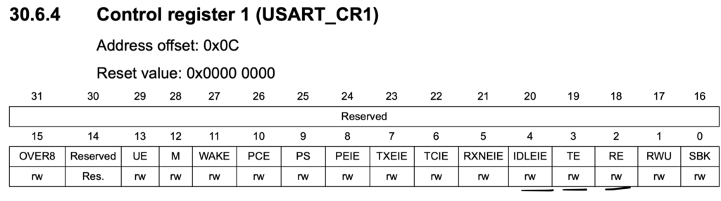
/*Configure UART*/
	USART2->BRR  = 0x0681;    //9600 @16MHz
	USART2->CR1|=USART_CR1_TE|USART_CR1_RE;
Enable ILDE line interrupt:
USART2->CR1|=USART_CR1_IDLEIE;
Enable DMA for RX in CR3 as following:
USART2->CR3|=USART_CR3_DMAR;
Enable interrupt and UART as following:
	NVIC_EnableIRQ(USART2_IRQn);
	USART2->CR1|=USART_CR1_UE;
For uart interrupt handler:
void USART2_IRQHandler(void)
{
    if (USART2->SR & USART_SR_IDLE) {

    done =1;
    (void)USART2->DR;
	DMA1_Stream5->CR &= ~DMA_SxCR_EN;         /* disable DMA1 Stream 5 */
	while (DMA1_Stream5->CR & DMA_SxCR_EN) {} /* wait until DMA1 Stream 5 is disabled */

    }

}
In order to clear the IDLE line interrupt, we need to read the SR followed by reading the DR register.
3. DMA configuration:
The DMA configuration is similar to the previous guide and the difference is we shall not use circular mode:
RCC->AHB1ENR |= RCC_AHB1ENR_DMA1EN;
	DMA1_Stream5->CR &= DMA_SxCR_EN;         /* disable DMA1 Stream 5 */
	while (DMA1_Stream5->CR & DMA_SxCR_EN) {} /* wait until DMA1 Stream 5 is disabled */

	DMA1->HIFCR|=DMA_HIFCR_CDMEIF5|DMA_HIFCR_CFEIF5|DMA_HIFCR_CTCIF5|DMA_HIFCR_CHTIF5|DMA_HIFCR_CTCIF5;

	DMA1_Stream5->PAR =(uint32_t)&USART2->DR;
	DMA1_Stream5->M0AR = (uint32_t)(&char_data[0]);
	DMA1_Stream5->NDTR = buffer_size;

	DMA1_Stream5->CR =(1<<27);
	DMA1_Stream5->CR|=(1<<10)|(1<<4);
	DMA1_Stream5->CR|=(1<<0);
DMA interrupt handler:
void DMA1_Stream5_IRQHandler(void)
		{
		if((DMA1->HISR)&(1<<11)) //DMA receive complete
			{
			DMA1->HIFCR|=(1<<11);
			}
		}
4. Code:
The entire code can be found here:
#include "stm32f4xx.h"
#include <stdlib.h>
#include <string.h>
#include <stdio.h>

#define buffer_size 100
uint8_t char_data[buffer_size];
volatile uint8_t done=0,done_rec;
#define AF07 0x07

void UART_Write_String(char *p);
void flush_buffer();
void reload();

int main(void)
{
	/*Enable clock access to GPIOA and USART2*/
	RCC->APB1ENR|=RCC_APB1ENR_USART2EN;
	RCC->AHB1ENR|=RCC_AHB1ENR_GPIOAEN;
	/*Configure the GPIO for UART Mode*/
	GPIOA->MODER|=GPIO_MODER_MODE2_1;//set bit5
	GPIOA->MODER&=~GPIO_MODER_MODE2_0;//reset bit4
	GPIOA->MODER|=GPIO_MODER_MODE3_1;//set bit7
	GPIOA->MODER&=~GPIO_MODER_MODE3_0;//reset bit6
	GPIOA->AFR[0]|=(AF07<<GPIO_AFRL_AFSEL2_Pos)|(AF07<<GPIO_AFRL_AFSEL3_Pos); //ALT7 for UART2 (PA2 and PA3)

	/*Configure UART*/
	USART2->BRR  = 0x0681;    //9600 @16MHz
	USART2->CR1|=USART_CR1_TE|USART_CR1_RE;
	USART2->CR1|=USART_CR1_IDLEIE;
	USART2->CR3|=USART_CR3_DMAR;
	NVIC_EnableIRQ(USART2_IRQn);
	USART2->CR1|=USART_CR1_UE;
	/*Configure the DMA*/
	RCC->AHB1ENR |= RCC_AHB1ENR_DMA1EN;
	DMA1_Stream5->CR &= DMA_SxCR_EN;         /* disable DMA1 Stream 5 */
	while (DMA1_Stream5->CR & DMA_SxCR_EN) {} /* wait until DMA1 Stream 5 is disabled */
	/*Clear DMA1_Stream5 interrupts*/
	DMA1->HIFCR|=DMA_HIFCR_CDMEIF5|DMA_HIFCR_CFEIF5|DMA_HIFCR_CTCIF5|DMA_HIFCR_CHTIF5|DMA_HIFCR_CTCIF5;
	/*Memory and peripheral address and number of transfers*/
	DMA1_Stream5->PAR =(uint32_t)&USART2->DR;
	DMA1_Stream5->M0AR = (uint32_t)(&char_data[0]);
	DMA1_Stream5->NDTR = buffer_size;
	/*Confgiure the DMA*/
	DMA1_Stream5->CR =(1<<27);
	DMA1_Stream5->CR|=(1<<10)|(1<<4);
	DMA1_Stream5->CR|=(1<<0);
	UART_Write_String("hello world\r\n");
	while(1)
		{

		while (done==0);
		done=0;
		UART_Write_String((char*)char_data);
		flush_buffer();
		reload();


		}

}


void USART_write(int ch){
while(!(USART2->SR&0x0080)){
}
USART2->DR=(ch);
}

void UART_Write_String(char *p)
	{
	while(*p!='\0')
{
USART_write(*p);
p++;
}
}

void flush_buffer()
	{
	memset(char_data, 0, buffer_size);
	}

void reload()
	{

	DMA1->HIFCR|=DMA_HIFCR_CDMEIF5|DMA_HIFCR_CFEIF5|DMA_HIFCR_CTCIF5|DMA_HIFCR_CHTIF5|DMA_HIFCR_CTCIF5;
	DMA1_Stream5->PAR =(uint32_t)&USART2->DR;
	DMA1_Stream5->M0AR = (uint32_t)(&char_data[0]);
	DMA1_Stream5->NDTR = buffer_size;
	DMA1_Stream5->CR |= DMA_SxCR_EN;
	}


void USART2_IRQHandler(void)
{
    if (USART2->SR & USART_SR_IDLE) {

    done =1;
    (void)USART2->DR;
	DMA1_Stream5->CR &= ~DMA_SxCR_EN;         /* disable DMA1 Stream 5 */
	while (DMA1_Stream5->CR & DMA_SxCR_EN) {} /* wait until DMA1 Stream 5 is disabled */

    }

}


void DMA1_Stream5_IRQHandler(void)
		{
		if((DMA1->HISR)&(1<<11)) //DMA receive complete
			{
			DMA1->HIFCR|=(1<<11);
			}
		}
4. Demo:
Happy coding 🙂
Add Comment