In this guide on the internal RTC of STM32G0, we shall configure the RTC and display the time and date on the serial terminal.
In this guide, we shall cover the following:
- Internal RTC.
- Driver development.
- Results.
1. Internal RTC:
The RTC provides an automatic wakeup to manage all low-power modes.
The real-time clock (RTC) is an independent BCD timer/counter. The RTC provides a timeof-day clock/calendar with programmable alarm interrupts.
As long as the supply voltage remains in the operating range, the RTC never stops, regardless of the device status (Run mode, low-power mode or under reset).
The RTC is functional in Vbat mode.
RTC main features
The RTC supports the following features:
• Calendar with subsecond, seconds, minutes, hours (12 or 24 format), week day, date, month, year, in BCD (binary-coded decimal) format.
• Automatic correction for 28, 29 (leap year), 30, and 31 days of the month.
• Two programmable alarms.
• On-the-fly correction from 1 to 32767 RTC clock pulses. This can be used to synchronize it with a master clock.
• Reference clock detection: a more precise second source clock (50 or 60 Hz) can be used to enhance the calendar precision.
• Digital calibration circuit with 0.95 ppm resolution, to compensate for quartz crystal inaccuracy.
• Timestamp feature which can be used to save the calendar content. This function can be triggered by an event on the timestamp pin, or by a tamper event, or by a switch to V BAT mode.
• 17-bit auto-reload wakeup timer (WUT) for periodic events with programmable resolution and period.
The RTC is supplied through a switch that takes power either from the V present or from the V BAT pin.
The RTC clock sources can be:
• A 32.768 kHz external crystal (LSE)
• An external resonator or oscillator (LSE)
DD
supply when
• The internal low power RC oscillator (LSI, with typical frequency of 32 kHz)
• The high-speed external clock (HSE), divided by a prescaler in the RCC.
The RTC is functional in V BAT mode and in all low-power modes when it is clocked by the LSE. When clocked by the LSI, the RTC is not functional in V BAT mode, but is functional in all low-power modes.
All RTC events (Alarm, WakeUp Timer, Timestamp) can generate an interrupt and wakeup the device from the low-power modes.

For more information about the internal RTC, please refer to STM32G0x0 reference manual.
2. Driver Development:
We start of by creating new project with name of RTC. For how to create new project, please refer to this guide.
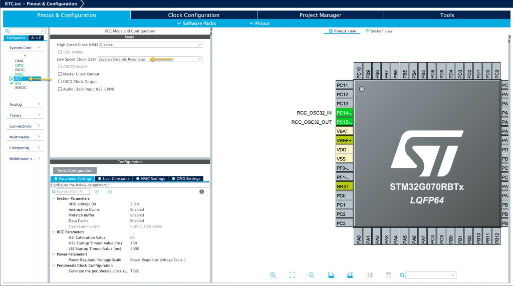
Once you have created your project, from System Core, select RCC and set Low Speed Clock (LSE) to be Crystal / Ceramic oscillator.
Note: If your board doesn’t have external LSE, skip this part.
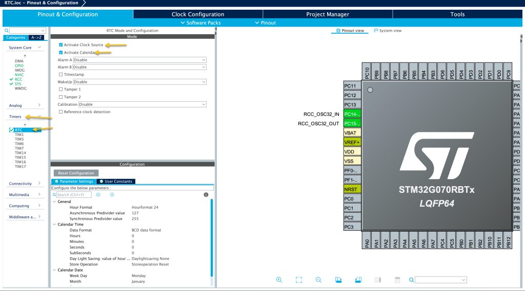
Then from timers, select RTC and select active clock source then activate calendar.
Leave the settings as is or set the time and date as your need.
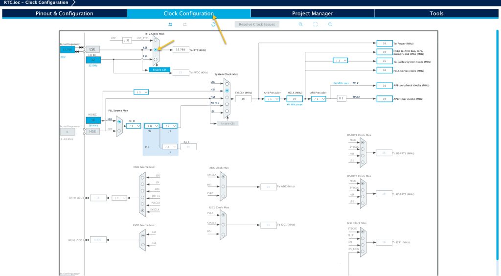
Next, from Clock Configuration tab, set LSE to be the RTC clock source as shown in figure below:
Skip this step if you are not using external oscillator.
Also, you need to enable the UART, please refer to this guide for how to enable the UART.
Save the project this shall generate the codes needed.
In main.c file.
In user begin includes, include the stdio header file as following:
/* USER CODE BEGIN Includes */
#include "stdio.h"
/* USER CODE END Includes */
Next, in user code begin PV, declare the following two data structure for the RTC operation:
/* USER CODE BEGIN PV */
RTC_TimeTypeDef gTime = {0};
RTC_DateTypeDef gDate = {0};
/* USER CODE END PV */
First data structure is to store the time while the second one is to store the date.
In user code begin 0, we shall retarget the printf to user UART as following:
int __io_putchar(int ch)
{
	HAL_UART_Transmit(&huart2, &ch, 1, 5);

	return ch;
}
This will allow us to use terminal to display the results.
In RTC_MX_Init function, at user code begin check_RTC_BKUP:
  /* USER CODE BEGIN Check_RTC_BKUP */
  if (HAL_RTCEx_BKUPRead(&hrtc, RTC_BKP_DR1)== 0x4567)
  {
	  return ;
  }
  /* USER CODE END Check_RTC_BKUP */
This line, will prevent entering new date and time once the MCU is reseted.
At user code begin RTC_Init_2, add this line:
  /* USER CODE BEGIN RTC_Init 2 */
  HAL_RTCEx_BKUPWrite(&hrtc, RTC_BKP_DR1, 0x4567);


  /* USER CODE END RTC_Init 2 */
By writing any value to the RTC backup register, this will lock the RTC from configuration. During the boot, we shall check this register if it has the same value, then no need to reinitialize the RTC data.
In while 1 loop, user code begin 3:
		if (HAL_RTC_GetTime(&hrtc, &gTime, RTC_FORMAT_BIN) != HAL_OK)
		{
			Error_Handler();
		}
		if(HAL_RTC_GetDate(&hrtc, &gDate, RTC_FORMAT_BIN)!=HAL_OK)
		{
			Error_Handler();
		}

		printf("Time is %d:%d:%d\r\n",gTime.Hours,gTime.Minutes,gTime.Seconds);
		printf("Date is %d/%d/%d\r\n",gDate.Date,gDate.Month,gDate.Year);
		HAL_Delay(500);
Read the RTC time and date.
Print the time and date.
Delay by 500ms.
3. Results:
Build and run the project on your STM32G070, open your serial terminal application and set the buadrate to 115200 and you should get the following:

Add Comment