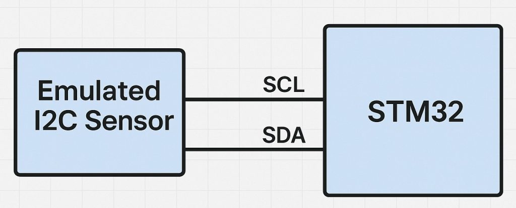
In this part of the guide, we will implement the functionality for the emulated sensor to receive configuration data from the I2C master. This allows the STM32-based emulator to mimic real sensor behavior when registers are written for settings or calibration.
In this guide, we shall cover the following:
- Introduction.
- Master firmware.
- Emulated sensor firmware.
- Results.
1. Introduction:
When emulating an I2C sensor using an STM32 microcontroller, one of the fundamental capabilities required is the ability to receive and process configuration data sent by the I2C master. Most I2C sensors on the market, such as accelerometers, gyroscopes, magnetometers, temperature sensors, and pressure sensors, have configurable registers that control their operating modes, measurement ranges, sampling rates, power management features, and interrupt configurations. For example, an accelerometer might have registers to set it into standby or active mode, adjust its sensitivity (e.g., ±2g, ±4g, ±8g), or configure high-pass filters and interrupt thresholds.
Why Receiving Configuration Data Matters in Emulation
Accurately emulating these configuration write operations is essential for:
- Realistic Sensor Behavior
Emulation is incomplete if it only returns hardcoded data. In practice, the master device (e.g., an MCU running an application) often writes to sensor configuration registers before reading measurement data. If these write operations are ignored, the master might assume a failure, halt initialization, or behave unpredictably. - Testing and Validation of Master Firmware
During embedded software development, developers need to verify that the master can correctly configure the sensor under different scenarios. Emulating these registers ensures the test environment behaves identically to the real hardware. - Simulating Power Modes and Operational States
Sensors often require specific initialization sequences. For instance, a temperature sensor might remain in shutdown mode until configuration bits are set to enable continuous conversion. Emulating this ensures that your STM32-based fake sensor properly replicates expected responses only when the sensor is configured for operation. - Emulating Calibration and Offset Registers
Many sensors allow writing calibration data (offsets, scale factors) into their internal registers to correct measurement errors. Proper emulation enables testing how the master handles these calibrations and whether it stores and retrieves them as intended.
2. Master Firmware:
For the master firmware, we shall assume that the emulated sensor has configuration register with address of 0x00 with initial value of 0, means everything is disabled for example. The master shall send the address 0x00 with randomized value.
Hence, open main.c file in the master project. We start by including the following library:
#include "stdlib.h"
This will allow us to use random function to generate random numbers.
Next, declare a buffer to store the slave register address and the data as follows:
uint8_t SlaveData[2];
In while 1 loop:
Store the register address and the randomized value to the array as follows:
SlaveData[0]=0x00;
SlaveData[1]=(rand()%255);
rand()%255 will limit the value of the random to 255.
Transmit the buffer in polling mode:
HAL_I2C_Master_Transmit(&hi2c1, (0x1D<<1), &SlaveData, 2, 100);
Delay by 100ms between each transmission:
HAL_I2C_Master_Transmit(&hi2c1, (0x1D<<1), &SlaveData, 2, 100);
Thats all for the master configuration. Save the project and run it on your MCU as follows:

Thats all for the master configuration.
3. Emulated Sensor Firmware:
Open main.c of the sensor emulation project.
In user PV, declare the following variables:
uint8_t RegisterData[10];

uint8_t counter;
- Array to store the incoming data from the master.
- counter to count the successful reception of the data.
In user code begin 2 in main function, start I2C listen in interrupt mode as follows:
HAL_I2C_EnableListen_IT(&hi2c1);
This function will listen to the address, once the address is matched, the following function shall be called which declared in user begin code 0:
void HAL_I2C_AddrCallback(I2C_HandleTypeDef *hi2c, uint8_t TransferDirection, uint16_t AddrMatchCode)
{

	if(hi2c->Instance==I2C1)
	{

		if(TransferDirection==I2C_DIRECTION_TRANSMIT)
		{
			HAL_I2C_Slave_Seq_Receive_IT(hi2c, (uint32_t)RegisterData, 2, I2C_FIRST_AND_LAST_FRAME);
		}

		else
		{
			//TODO
		}


	}

}
As soon as the master sends an address on the I2C bus that matches the STM32’s configured slave address, this callback is triggered.
Key parameters:
- TransferDirection indicates whether the master wants to write to the slave (I2C_DIRECTION_TRANSMIT) or read from the slave (I2C_DIRECTION_RECEIVE).
- AddrMatchCode is the matched address, useful if multiple slave addresses are configured.
Step-by-Step Explanation
- Function Purpose
This function is the address callback automatically called by the HAL library when the I2C peripheral detects communication from a master matching its configured slave address. - Parameter Summary
- hi2c: The I2C handle pointing to the specific peripheral (e.g. I2C1).
- TransferDirection: Indicates whether the master intends to write to or read from the slave.
- AddrMatchCode: The detected address that matched the STM32 slave configuration.
- Peripheral Instance Check
The function first checks which I2C instance triggered the callback. This ensures the logic only executes for the intended peripheral (e.g. I2C1) in projects with multiple I2C buses. - Communication Direction Decision
- If the master wants to write data to the slave (transmit direction), the STM32 prepares itself to receive data bytes.
- Specifically, it sets up a buffer to receive 2 bytes via interrupt mode, allowing asynchronous reception while the main code continues running.
- Handling Master Read Requests
- If the master wants to read data from the slave (receive direction), this part is currently unimplemented (marked as TODO).
- In a complete emulation, you would prepare the data to be sent back to the master in this branch.
- Overall Behavior
This callback ensures that the STM32, acting as an emulated I2C sensor, correctly responds to whether the master is writing configuration data or reading sensor data, initiating the appropriate receive or transmit sequence accordingly.
Once all the data has been received, the following function shall be called:
void HAL_I2C_SlaveRxCpltCallback(I2C_HandleTypeDef *hi2c)
{
	if(hi2c->Instance==I2C1)
	{
		counter++;
	}
}
Function Purpose
This function is the Slave Receive Complete Callback. It is automatically called by the HAL library when the STM32, acting as an I2C slave, has successfully received all the data bytes sent by the master in a write operation.
Finally, listen completed callback shall be called:
void HAL_I2C_ListenCpltCallback(I2C_HandleTypeDef *hi2c)
{
	if(hi2c->Instance==I2C1)
	{
		HAL_I2C_EnableListen_IT(hi2c);
	}

}
Within the listen completed callback, start listen process again to get the new data.
That all for the emulated sensor. Save the project and start a debugging session as follows:

4. Results:
By adding RegisterData and counter to Liver Expression, you should get the following:
Next part, we shall transmit data from the emulated sensor to the master.
Stay tuned and happy coding 😉
Add Comment