In this series of guide, we shall use STM32CubeIDE with STM32CubeMX integration with IDE to drive the peripheral of the STM32G070.
In this guide, we shall cover the following:
- STM32G070 Features.
- Hardware connection.
- Project setup.
- Blinking LED code.
- Results.
1. STM32G070 Features:
The STM32G070CB/KB/RB mainstream microcontrollers are based on high-performance Arm® Cortex®-M0+ 32-bit RISC core operating at up to 64 MHz frequency. Offering a high level of integration, they are suitable for a wide range of applications in consumer, industrial and appliance domains and ready for the Internet of Things (IoT) solutions.
The devices incorporate a memory protection unit (MPU), high-speed embedded memories (128 Kbytes of Flash program memory with read protection, write protection, and 36 Kbytes of SRAM), DMA and an extensive range of system functions, enhanced I/Os and peripherals. The devices offer standard communication interfaces (two I2Cs, two SPIs / one I2S, and four USARTs), one 12-bit ADC (2.5 MSps) with up to 19 channels, a low-power RTC, an advanced control PWM timer, five general-purpose 16-bit timers, two basic timers, two watchdog timers, and a SysTick timer.
The devices operate within ambient temperatures from -40 to 85°C. They can operate with supply voltages from 2.0 V to 3.6 V. Optimized dynamic consumption combined with a comprehensive set of power-saving modes allows the design of low-power applications.
VBAT direct battery input allows keeping RTC and backup registers powered.
The devices come in packages with 32 to 64 pins.
- All features
- Core: Arm® 32-bit Cortex®-M0+ CPU, frequency up to 64 MHz
- -40°C to 85°C operating temperature
- Memories
- 128 Kbytes of Flash memory with protection
- 36 Kbytes of SRAM (32 Kbytes with HW parity check)
- CRC calculation unit
- Reset and power management
- Voltage range: 2.0 V to 3.6 V
- Power-on/Power-down reset (POR/PDR)
- Low-power modes:Sleep, Stop, Standby
- VBAT supply for RTC and backup registers
- Clock management
- 4 to 48 MHz crystal oscillator
- 32 kHz crystal oscillator with calibration
- Internal 16 MHz RC with PLL option
- Internal 32 kHz RC oscillator (±5 %)
- Up to 59 fast I/Os
- All mappable on external interrupt vectors
- Multiple 5 V-tolerant I/Os
- 7-channel DMA controller with flexible mapping
- 12-bit, 0.4 µs ADC (up to 16 ext. channels)
- Up to 16-bit with hardware oversampling
- Conversion range: 0 to 3.6V
- 11 timers: 16-bit for advanced motor control, five 16-bit general-purpose, two basic 16-bit, two watchdogs, SysTick timer
- Calendar RTC with alarm and periodic wakeup from Stop/Standby
- Communication interfaces
- Two I2C-bus interfaces supporting Fast-mode Plus (1 Mbit/s) with extra current sink, one supporting SMBus/PMBus and wakeup from Stop mode
- Four USARTs with master/slave synchronous SPI; two supporting ISO7816 interface, LIN, IrDA capability, auto baud rate detection and wakeup feature
- Two SPIs (32 Mbit/s) with 4- to 16-bit programmable bitframe, one multiplexed with I2S interface
- Development support: serial wire debug (SWD).

Note: Taken from ST website.
2. Hardware Connection:
Before heading into the programming section, we shall connect the LED to PA0 with 100 Ohm resistor in series as shown in the figure below:

3. Project Setup:
First step open STM32CubeIDE.
This window will appear:
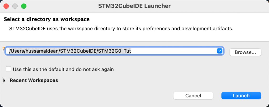
Give the workspace a name for example STM32G0_Tut.
Once you click on launch. we shall start new project as following:
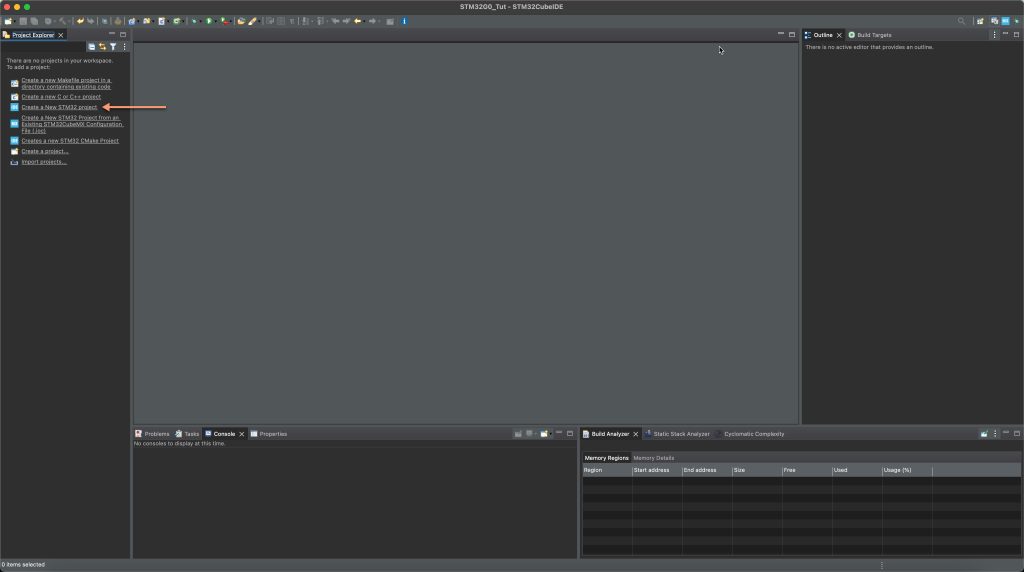
From left window, click on Create new STM32 Project.
Then, type your STM32G0 exact number (STM32G070RB in this case)

Select the MCU from the list and click on next.
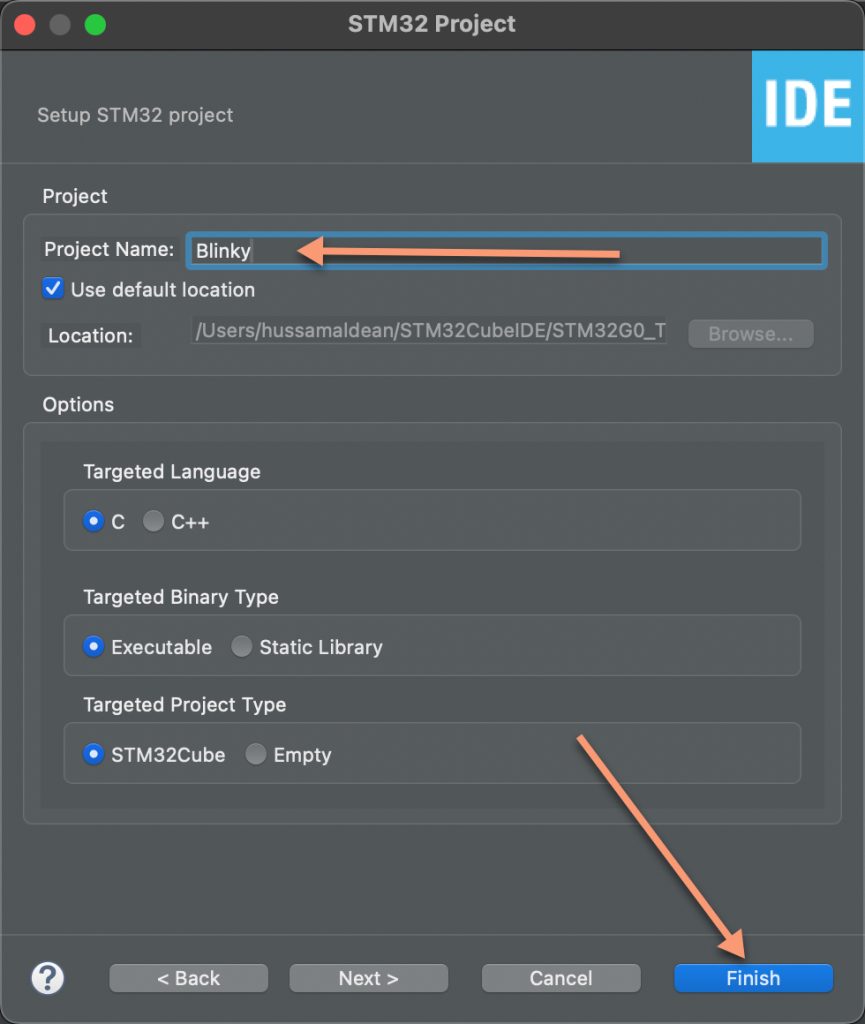
Next, give the project a name which is in this case blinky and click on finish.
At this stage, if you don’t have the package, it will download the package. So, please be patient with this process.
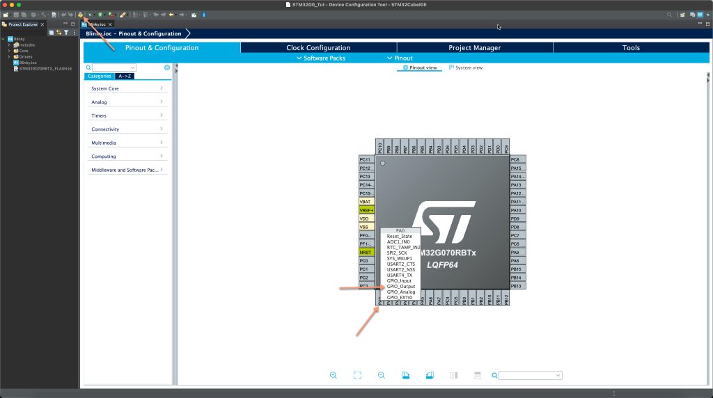
This window will appear, click on PA0 and select GPIO Output and then press on code generate (the gear icon)
Now, the IDE will open main.c.
In main.c, add the following code at User Code begin 3:
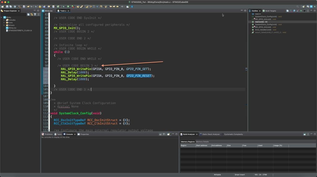
	  HAL_GPIO_WritePin(GPIOA, GPIO_PIN_0, GPIO_PIN_SET);
	  HAL_Delay(1000);
	  HAL_GPIO_WritePin(GPIOA, GPIO_PIN_0, GPIO_PIN_RESET);
	  HAL_Delay(1000);
Or
	  HAL_GPIO_TogglePin(GPIOA, GPIO_PIN_0);
	  HAL_Delay(1000);
Upload the code to your board and you should notice the LED is blinking.
4. Demo:
Happy coding 🙂
Add Comment