In the previous guide (here), we took a look at the SPI interface and how to configure the STM32G0 to communicate with SPI slave device (MPU9250) in polling mode. In this guide, we shall transmit data over SPI bus using DMA.
In this guide, we shall cover the following:
- SPI DMA configuration.
- Transmitting data.
- Results.
1. SPI DMA Configuration:
We start off by creating new project with name of SPI_Full_Duplex. For how to create new project from scratch, please refer to this guide.
Then from pinout and configuration:
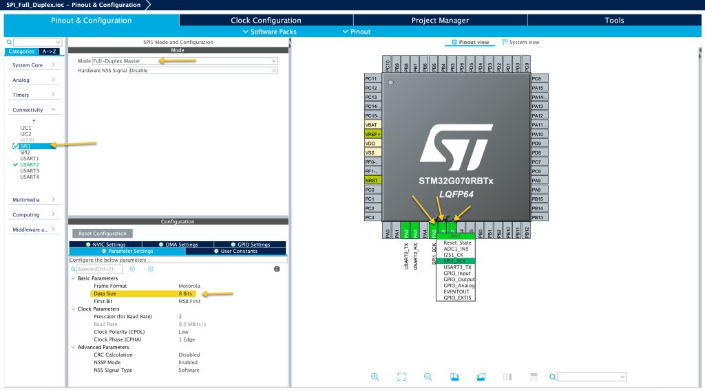
Select PA5, PA6 and PA7 for SPI1 as shown in the picture.
From connectivity, enable SPI1 to be full duplex Master mode.
Set the data size to 8-bit.
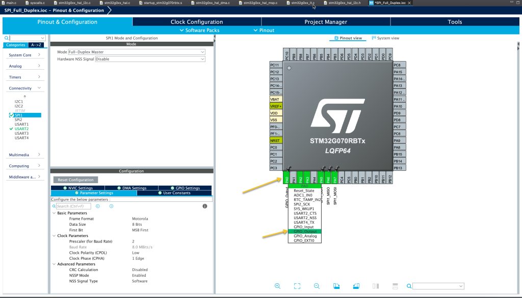
Next, set PA0 as GPIO to act as CS line as following:
From DMA Settings of SPI:
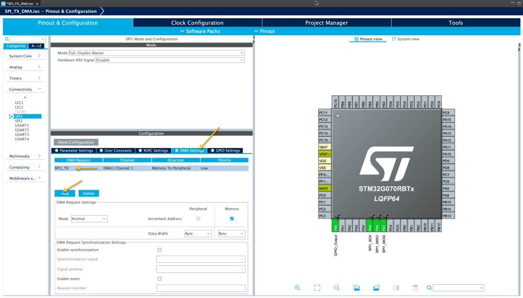
Enable SPI_TX and keep everything as default.
In NVIC Settings:
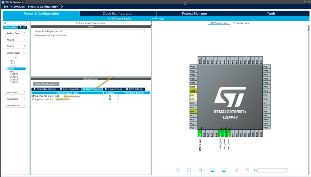
Make sure to enable SPI Global interrupt.
Save the project and this shall generate the code.
2. Transmitting Data:
In main.c file.
In user code begin PV:
Declare the following variable as volatile since this will be handled in the interrupt handler function.
volatile uint8_t TXfinished=0;
Declare an array to hold the data to be send:
#define data_size 5

uint8_t TXdata[data_size]={0x01,0x02,0x03,0x04,0x05};
In this example, we are using an array of size 5, you can go up to 65K.
In user code begin 4:
This function shall be called once the SPI in either in interrupt or DMA mode finished transferring the data:
void HAL_SPI_TxCpltCallback(SPI_HandleTypeDef *hspi)
{
	TXfinished=1;
}
Within the function, we shall set TXfinished to 1 to flag our application that SPI finished the transmission of the data.
In user code begin 3:
Set PA0 to low to which is the CS pin:
	  /*Set PA0 to LOW*/
	  HAL_GPIO_WritePin(GPIOA, GPIO_PIN_0, GPIO_PIN_RESET);
Transmit the data:
	  /*Transmit the data over SPI using DMA*/
	  HAL_SPI_Transmit_DMA(&hspi1, &TXdata, data_size);
The function takes three parameters:
- Handle to the SPI to be used (hspi1 in this case).
- Array that hold the data to be send.
- Size of the data to be transmitted.
Then wait for the transfer to complete and reset the variable:
	  /*Wait until the data is transmitted*/
	  while(TXfinished==0)
	  {
		  ;
	  }
	  TXfinished=0;
Set PA0 to high:
	  /*Set PA0 to HIGH*/
	  HAL_GPIO_WritePin(GPIOA, GPIO_PIN_0, GPIO_PIN_SET);
Save the project, build and run on your STM32G070 MCU.
3. Results:
By probing PA0, PA5, PA6 and PA7 using logic analyzer, you should get the following:

Happy coding 😉
Add Comment