In this guide, we shall configure the SPI of the STM32G070 to communicate with a slave device (MPU9250 in this case) and get the acceleration and gyroscope data.
In this guide, we shall cover the following:
- What is SPI.
- SPI Configuration.
- MPU9250 Source and header file.
- Main source code.
- MPU9250 Connection.
- Results.
1. What is SPI:
SPI, which stands for Serial Peripheral Interface, is a standard with a very specific hardware interface. A connection is between a master and a slave, with the master typical being a processor, and the slave being a peripheral such as a sensor, flash memory device, or a modem chip. It can also be used for processor to processor communications, but in this case, an additional handshake signal is often used. There are normally four signals between a master and a slave, the first is a clock signal, and this signal is always driven by the master, regard which device is transmitting. The second line is a data line for data going from the master to the slave, and this is designated as the master output, slave input line, are MOSI for short. It connects the SPI data out connection on the master and to the SPI data in connection on the slave.
The next conductor is for data in the opposite direction and is labelled as the master input slave output line, are MISO for short. The last conductor is slave select with the slave chip selecting input, and is active low.

If you have more than one slave, with the first being perhaps a sensor of some kind, the slave will be dedicated to slave 1. If you add a second sensor, the top 3 interface line will be shared, but it dedicates for slave’s line will be required for the second device, and the same is true of course for each of additional slave device.

Most processors have a maxim of 4 slave selected lines. The four lines could be used effectively as a multiplexed address lines to access more than 4 slaves. You cannot have more than one master on the bus, since the interface is not support coordination between two masters as to which one is controlling the bus.
Transmissions are typically sent as a sequence of bytes, but without a formal protocol, there is nothing restricting communication being byte based. Typical by frame sizes, are in 8 to 32 bits range. Also note the bytes and packets are not acknowledged as they are in i2c, and you could have a master synching communicating with the slave but, you don’t really know of your communications are being received OK. However, some slave devices will echo bytes sent to it, which provides an acknowledgement to the master. it is how the data lines are synchronized with a clock signal.
Clock Polarity and Phasing
There are four different modes available, one mode each combination clocking in a low state and high state, with a data being read in a rising edge or falling edge of the clock signal. For modes 0 and 1, the clock is low in idle, which is referred to as clock and 0, For modes 2 and 3 then the clock is in high state when idle, so it has polarity , one , For modes 0 and 2, the data will be sampled by the receiving device on the leading edge of a clock signal. Relative to the idle state, which is referred to a clock phase of zero. So for mode 0, this means the rising edge of the clock and for mode 2, means the following edge of the clock, the other two modes, use a clock phase 1 which means that trailing edge of clock as a returns to an idle state. And this translates to a following edge for mode 1 and the rising edge for mode 3. Mode 0 is the most commonly supported setting. If multiple slaves in the same bus, you may have to reconfigure the settings for the master to which modes when you want to communicate with a different slave.

2. SPI Configuration:
We start off by creating new project with name of SPI_Full_Duplex. For how to create new project from scratch, please refer to this guide.
Then from pinout and configuration:
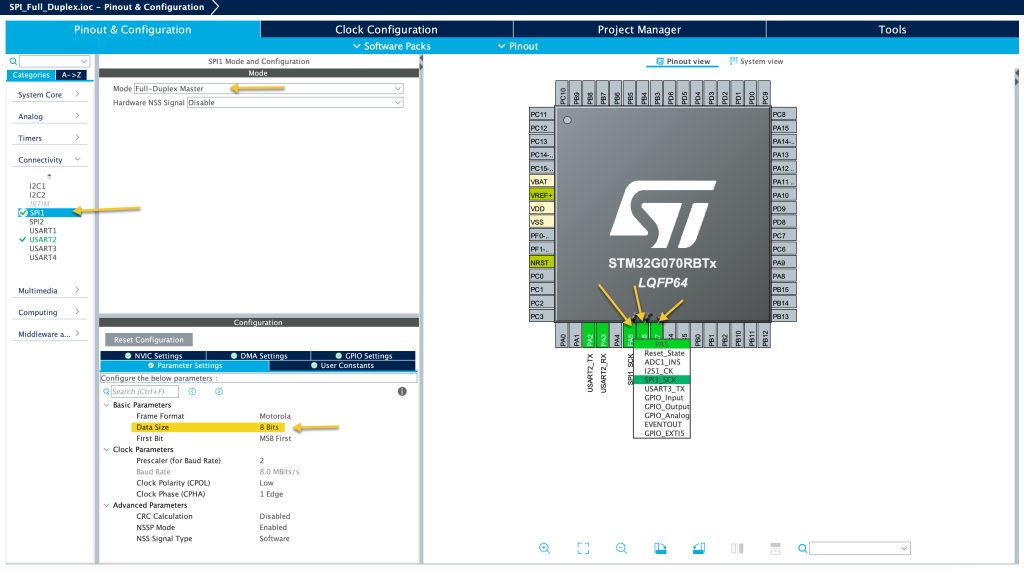
Select PA5, PA6 and PA7 for SPI1 as shown in the picture.
From connectivity, enable SPI1 to be full duplex Master mode.
Set the data size to 8-bit.
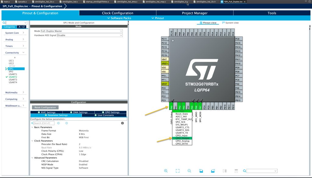
Next, set PA0 as GPIO to act as CS line as following:
Also, enable UART, for more details, please refer to this guide.
Save the project and this should generate the code.
3. MPU9250 source and header file modification:
Before modification, please refer to this guide for MPU9250.
header file:
#ifndef __MPU9250__H__
#define __MPU9250__H__

#include "stdint.h"

#define Pi 3.14159
#define MPU9250_ADDRESS_AD0_LOW  0x68
#define MPU9250_ADDRESS_AD0_HIGH 0x69

#define ACC_FULL_SCALE_2_G       0x00
#define ACC_FULL_SCALE_4_G       0x08
#define ACC_FULL_SCALE_8_G       0x10
#define ACC_FULL_SCALE_16_G      0x18

#define GYRO_FULL_SCALE_250_DPS  0x00
#define GYRO_FULL_SCALE_500_DPS  0x08
#define GYRO_FULL_SCALE_1000_DPS 0x10
#define GYRO_FULL_SCALE_2000_DPS 0x18

#define MAG_MODE_POWERDOWN        0x0
#define MAG_MODE_SINGLE           0x1
#define MAG_MODE_CONTINUOUS_8HZ   0x2
#define MAG_MODE_EXTERNAL         0x4
#define MAG_MODE_CONTINUOUS_100HZ 0x6
#define MAG_MODE_SELFTEST         0x8
#define MAG_MODE_FUSEROM          0xF
#define AK8963_ADDRESS  0x0C
#define AK8963_RA_HXL   0x03
#define AK8963_RA_CNTL1 0x0A
#define AK8963_RA_ASAX  0x10

#define MPU9250_ADDR_ACCELCONFIG  0x1C
#define MPU9250_ADDR_INT_PIN_CFG  0x37
#define MPU9250_ADDR_ACCEL_XOUT_H 0x3B
#define MPU9250_ADDR_GYRO_XOUT_H  0x43
#define MPU9250_ADDR_PWR_MGMT_1   0x6B
#define MPU9250_ADDR_WHOAMI       0x75
#define address 0x68
//accelerartion part
void MPU9250_beginAccel(uint8_t mode);
float MPU9250_accelX(void);
float MPU9250_accelY(void);
float MPU9250_accelZ(void);
uint8_t MPU9250_accelUpdate(void);


//gyro part
void MPU9250_beginGyro(uint8_t mode);
uint8_t MPU9250_gyroUpdate(void);
float MPU9250_gyroX(void);
float MPU9250_gyroY(void);
float MPU9250_gyroZ(void);


#endif
The modification as following:
- Remove the inclusion of delay header file.
Source code:
#include <math.h>
#include "MPU9250.h"
#include "main.h"


double accelRange,gyroRange;
uint8_t magBuf[7], magXAdjust, magYAdjust, magZAdjust;
uint8_t accelBuf[6],gyroBuf[6];
uint8_t magBuf[7];
int i;
int16_t magXOffset, magYOffset, magZOffset;


extern SPI_HandleTypeDef hspi1;


#define READ_FLAG   0x80


//start Accelerometer
void MPU9250_beginAccel(uint8_t mode) {
  switch(mode) {
  case ACC_FULL_SCALE_2_G:
    accelRange = 2.0;
    break;
  case ACC_FULL_SCALE_4_G:
    accelRange = 4.0;
    break;
  case ACC_FULL_SCALE_8_G:
    accelRange = 8.0;
    break;
  case ACC_FULL_SCALE_16_G:
    accelRange = 16.0;
    break;
  default:
    return; // Return without writing invalid mode
  }

  uint8_t data[2]={MPU9250_ADDR_ACCELCONFIG,mode};
  HAL_GPIO_WritePin(GPIOA, GPIO_PIN_0,GPIO_PIN_RESET);
  HAL_SPI_Transmit(&hspi1, data, 2, 100);
  HAL_GPIO_WritePin(GPIOA, GPIO_PIN_0,GPIO_PIN_SET);

}

//start gyroscope
void MPU9250_beginGyro(uint8_t mode) {

  switch (mode) {
  case GYRO_FULL_SCALE_250_DPS:
    gyroRange = 250.0;
    break;
  case GYRO_FULL_SCALE_500_DPS:
    gyroRange = 500.0;
    break;
  case GYRO_FULL_SCALE_1000_DPS:
    gyroRange = 1000.0;
    break;
  case GYRO_FULL_SCALE_2000_DPS:
    gyroRange = 2000.0;
    break;
  default:
    return; // Return without writing invalid mode
  }
  uint8_t data[2]={27,mode};
  HAL_GPIO_WritePin(GPIOA, GPIO_PIN_0,GPIO_PIN_RESET);
  HAL_SPI_Transmit(&hspi1, data, 2, 100);
  HAL_GPIO_WritePin(GPIOA, GPIO_PIN_0,GPIO_PIN_SET);
}

//start compass


uint8_t MPU9250_accelUpdate(void)
{
	uint8_t data=0x3B|READ_FLAG;
	HAL_GPIO_WritePin(GPIOA, GPIO_PIN_0,GPIO_PIN_RESET);

	HAL_SPI_Transmit(&hspi1, &data,1,100);
	HAL_SPI_Receive(&hspi1, accelBuf, 6, 100);

	HAL_GPIO_WritePin(GPIOA, GPIO_PIN_0,GPIO_PIN_SET);
	return 0;

}

float MPU9250_accelGet(uint8_t highIndex, uint8_t lowIndex) {
  int16_t v = ((int16_t) accelBuf[highIndex]) << 8 | accelBuf[lowIndex];
  return ((float) -v) * accelRange / (float) 0x8000; // (float) 0x8000 == 32768.0
}

float MPU9250_accelSqrt(void) {
  return sqrt(pow(MPU9250_accelGet(0, 1), 2) +
              pow(MPU9250_accelGet(2, 3), 2) +
              pow(MPU9250_accelGet(4, 5), 2));
}

float MPU9250_accelX(void) {
  return MPU9250_accelGet(0, 1);
}

float MPU9250_accelY(void) {
  return MPU9250_accelGet(2, 3);
}

float MPU9250_accelZ(void) {
  return MPU9250_accelGet(4, 5);
}


uint8_t MPU9250_gyroUpdate(void)
{
	uint8_t data=0x43|READ_FLAG;

	HAL_GPIO_WritePin(GPIOA, GPIO_PIN_0,GPIO_PIN_RESET);

	HAL_SPI_Transmit(&hspi1, &data,1,100);
	HAL_SPI_Receive(&hspi1, gyroBuf, 6, 100);

	HAL_GPIO_WritePin(GPIOA, GPIO_PIN_0,GPIO_PIN_SET);
	return 0;
}

float MPU9250_gyroGet(uint8_t highIndex, uint8_t lowIndex) {
  int16_t v = ((int16_t) gyroBuf[highIndex]) << 8 | gyroBuf[lowIndex];
  return ((float) -v) * gyroRange / (float) 0x8000;
}

float MPU9250_gyroX(void) {
  return MPU9250_gyroGet(0, 1);
}

float MPU9250_gyroY(void) {
  return MPU9250_gyroGet(2, 3);
}

float MPU9250_gyroZ(void) {
  return MPU9250_gyroGet(4, 5);
}
The modification as following:
- Remove the inclusion of spi header file.
- Include main.h header file
- Declare this extern SPI_HandleTypeDef hspi1; to handle the SPI communication.
- Replace cs_loe() with HAL_GPIO_WritePin(GPIOA, GPIO_PIN_0,GPIO_PIN_RESET);
- Replace spi_transmit with HAL_SPI_Transmit(&hspi1, data, 2, 100);
- replace cs_high() with HAL_GPIO_WritePin(GPIOA, GPIO_PIN_0,GPIO_PIN_SET);
- For the acceleration update function:
	HAL_GPIO_WritePin(GPIOA, GPIO_PIN_0,GPIO_PIN_RESET);

	HAL_SPI_Transmit(&hspi1, &data,1,100);
	HAL_SPI_Receive(&hspi1, accelBuf, 6, 100);

	HAL_GPIO_WritePin(GPIOA, GPIO_PIN_0,GPIO_PIN_SET);
For the gyroscope update function:
uint8_t MPU9250_gyroUpdate(void)
{
	uint8_t data=0x43|READ_FLAG;

	HAL_GPIO_WritePin(GPIOA, GPIO_PIN_0,GPIO_PIN_RESET);

	HAL_SPI_Transmit(&hspi1, &data,1,100);
	HAL_SPI_Receive(&hspi1, gyroBuf, 6, 100);

	HAL_GPIO_WritePin(GPIOA, GPIO_PIN_0,GPIO_PIN_SET);
	return 0;
}
The rest shall remain the same.
4. Main source code:
In main c:
In user code begin includes, include the following:
#include "MPU9250.h"
#include "stdio.h"
In user code begin 0, declare the following function:
int __io_putchar(int ch)
{
	HAL_UART_Transmit(&huart2, &ch, 1, 10);
	return ch;
}
This will redirect the printf to use serial.
In user code begin 2:
  MPU9250_beginAccel(ACC_FULL_SCALE_16_G);
  MPU9250_beginGyro(GYRO_FULL_SCALE_2000_DPS);
Initialize both the accelerometer and gyroscope.
In code begin 3:
		MPU9250_accelUpdate();
		MPU9250_gyroUpdate();
		printf("Acceleration data %0.3f %0.3f %0.3f \r\n",MPU9250_accelX(),(MPU9250_accelY()-(float)3.5),MPU9250_accelZ());
		printf("Gyroscope data %0.3f %0.3f %0.3f \r\n",MPU9250_gyroX(),MPU9250_gyroY(),MPU9250_gyroZ());
		HAL_Delay(200);
In order to let printf prints float values, we need to enable it.
Right click on the project and select properties then follow the following:
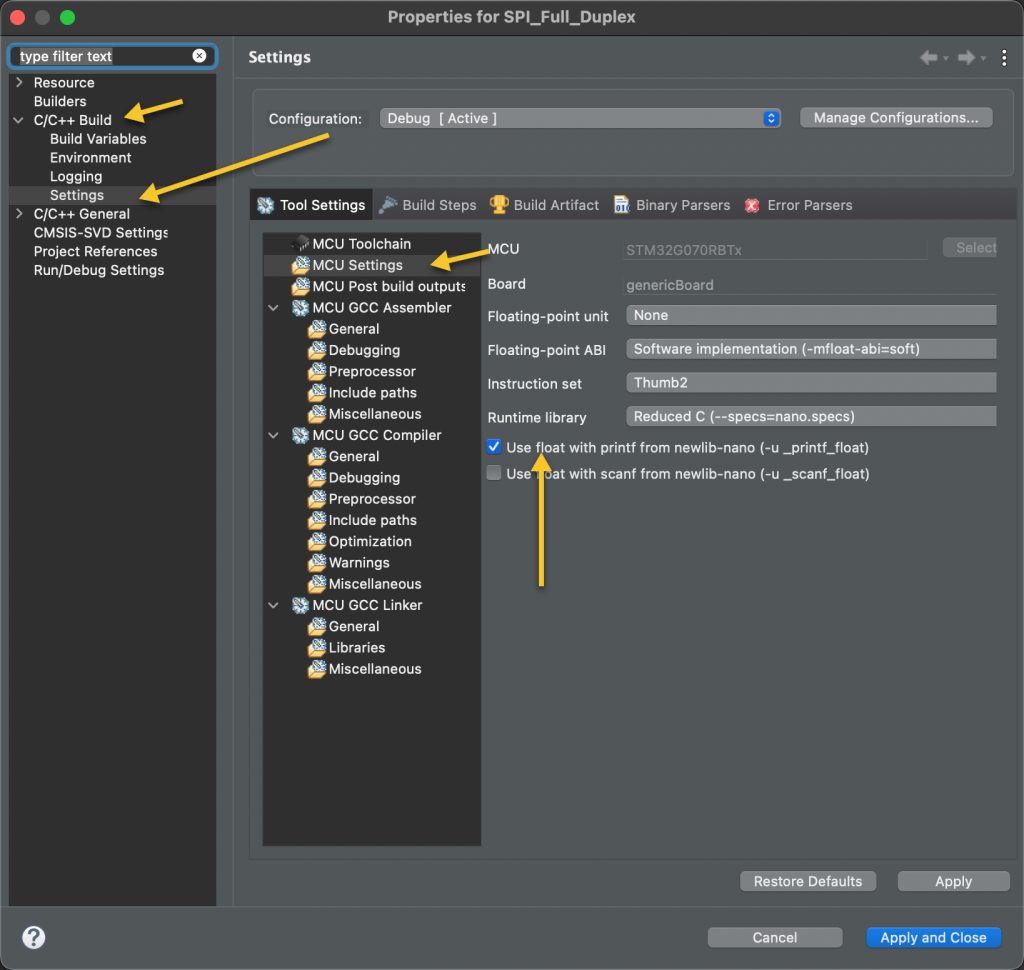
Click on apply and close.
5. Connection:
The connection as following:
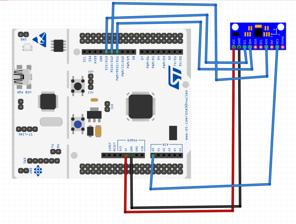
6. Results:
Open your serial monitor application, select the COM port and set the baud to be 115200 and you should get the following:

Happy coding 😉
Add Comment