
In this guide on STM32H5 series, we shall see how to configure the GPIO as input, read the state of the pin and reflect this state to the LEDs on our Nucleo board.
In this guide, we shall cover the following:
- Input modes.
- Driver development.
- Results.
1. Input Modes:
GPIO input modes include
- high impedance
- pull-up
- pull-down
Floating, High Impedance, Tri-Stated
Floating, high impedance, and tri-stated are three terms that mean the same thing: the pin is just flopping in the breeze. Its state is indeterminate unless it is driven high or low externally. You only want to configure a pin as floating if you know it will be driven externally. Otherwise, configure the input using pulling resistors.
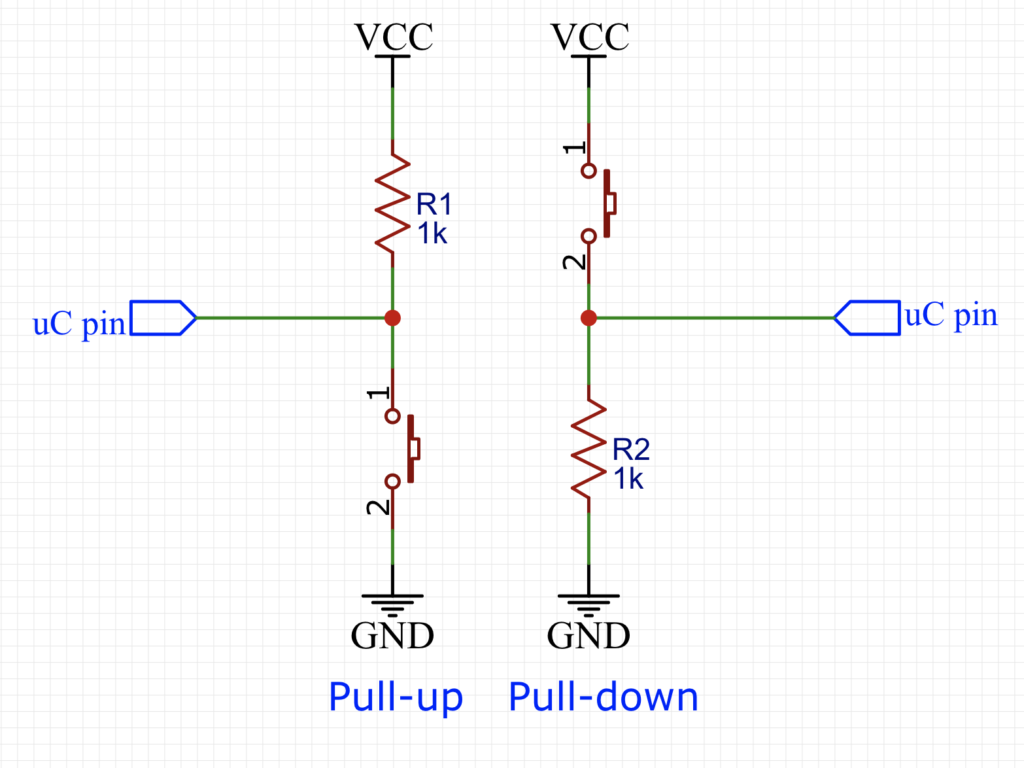
Pull Up/Down
If an input is configured with an internal pull-up, it will be high unless it is externally driven low. Pull-down inputs do the opposite ( they’re low unless driven high).
2. Driver development:
We start by creating new project and name it GPIO_Input. For how to create new project, please follow this guide from here.
Before we configure the pin, we need to get which pin is connected to the USER Button on the nucleo-144.
From the schematic, we can find this:
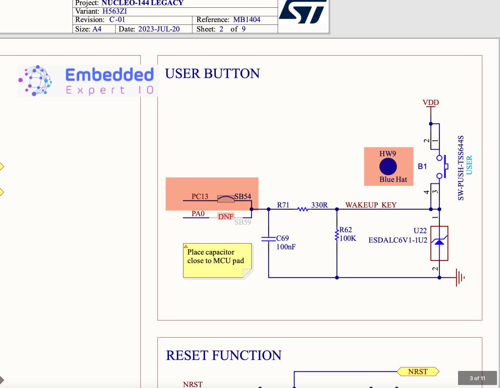
With the default configuration, the push button is connected to PC 13.
Since the configuration is pull down mode, which means that when the button is pressed, you will get 1 and 0 when released.
Hence, we can configure the PC13 as following:

Select PC13 and set it as GPIO input.
Also, enable PB0 as output to control the green LED of our Nucleo-144 board.
Note: If this windows didn’t appear, click on GPIO_Input.ioc and it will appear.
Next click on generate code as following:

After the code being generated, main.c will be open.
In user code 3, which is in while 1 loop, we shall read the pin and control the LED according to the state of the GPIO.
First, we need to declare a state variable to hold the state of the pin as following:
uint8_t state;
Next, we shall read the state of the pin and store it in the variable as following:
state=HAL_GPIO_ReadPin(GPIOC, GPIO_PIN_13);
The function HAL_GPIO_ReadPin(GPIOx, GPIO_Pin) will read a specific pin and return the state of the pin.
It takes the following arguments:
- GPIOx which GPIO port to be read, GPIOC in our case.
- GPIO_Pin which is which pin to be read, PIN13 in our case.
The function shall return the state of the pin as following:
- GPIO_PIN_RESET when it is low.
- GPIO_PIN_SET when it is high.
Next, we shall control the state of the LED according to the pin state as following:
HAL_GPIO_WritePin(GPIOB, GPIO_PIN_0, state);
Then delay by 10ms as following:
HAL_Delay(10);
Hence, the code as following:
uint8_t state;
state=HAL_GPIO_ReadPin(GPIOC, GPIO_PIN_13);
HAL_GPIO_WritePin(GPIOB, GPIO_PIN_0, state);
HAL_Delay(10);
That all for the guide.
Save the project, build it and run it on your STM32H563Zi board.

3. Results:
Happy coding 😉
Add Comment