
In this guide series, we shall cover the I2S peripheral of STM32F407 and its feature.
In this guide, we shall covet the following:
- What is I2S.
- Feature of I2S of STM32F407.
- Feature of CS43L22.
- Environment Setup.
- Set the core speed to 168MHz.
- Delay funciton.
- I2C Peripheral initialization.
1. What is I2S:
I²S (Inter-IC Sound), pronounced “eye-squared-ess,” is an electrical serial bus interface standard used for connecting digital audio devices together. It facilitates the communication of PCM (pulse-code modulated) audio data between integrated circuits within an electronic device. Here are some key details about I²S:
- Bus Configuration:
- The I²S bus consists of at least three lines:
- Bit Clock (BCLK): Also known as the “continuous serial clock,” this line synchronizes the data transmission. It pulses once for each discrete bit of data on the data lines.
- Word Clock (WS): Indicates whether channel 1 (WS = 0) or channel 2 (WS = 1) is being transmitted. I²S allows two channels to be sent on the same data line.
- Multiplexed Data Line (SD): Carries the actual audio data. It can be called by various names such as SDATA, SDIN, SDOUT, DACDAT, or ADCDAT.
- Optionally, there may be a Master Clock(typically 256 times the LRCLK) for synchronizing analog/digital converters.
- The I²S bus consists of at least three lines:
- Timing and Synchronization:
- The word select clock (WS) has a 50% duty cycle and the same frequency as the sample rate. For stereo material, left audio is transmitted during the low cycle of WS, and the right channel during the high cycle.
- Data is latched on the rising edge of the serial clock (SCK).
- History:
- Introduced by Philips Semiconductor (now NXP Semiconductors) in 1986.
- Last revised in February 2022, updating terms from “master” and “slave” to “controller” and “target”.
I²S is commonly used in audio codecs, microcontrollers, digital signal processors, and other sound-processing devices. It provides high-quality audio transmission, precise synchronization, and efficient data transfer, making it a preferred choice for digital audio communication
2. Feature of I2S of STM32F407:
Full duplex communication
• Half-duplex communication (only transmitter or receiver)
• Master or slave operations
• 8-bit programmable linear prescaler to reach accurate audio sample frequencies (from 8 kHz to 192 kHz)
• Data format may be 16-bit, 24-bit or 32-bit
• Packet frame is fixed to 16-bit (16-bit data frame) or 32-bit (16-bit, 24-bit, 32-bit data frame) by audio channel
• Programmable clock polarity (steady state)
• Underrun flag in slave transmission mode, overrun flag in reception mode (master and slave), and Frame Error flag in reception and transmission mode (slave only)
• 16-bit register for transmission and reception with one data register for both channel sides
• Supported I 2 S protocols:
– I 2 S Phillps standard
– MSB-justified standard (left-justified)
– LSB-justified standard (right-justified)
– PCM standard (with short and long frame synchronization on 16-bit channel frame or 16-bit data frame extended to 32-bit channel frame)
• Data direction is always MSB first
• DMA capability for transmission and reception (16-bit wide)
• Master clock may be output to drive an external audio component. Ratio is fixed at 256 × F S (where F S is the audio sampling frequency)
• Both I 2 S (I2S2 and I2S3) have a dedicated PLL (PLLI2S) to generate an even more accurate clock.
• I 2 S (I2S2 and I2S3) clock can be derived from an external clock mapped on the I2S_CKIN pin.

3. Feature of CS43L22:
The CS43L22 is a low-power stereo digital/analog converter (DAC) manufactured by Cirrus Logic. Let’s explore its key features:
- DAC and Amplifiers:
- The CS43L22 integrates both a headphone amplifier and a Class D speaker amplifier.
- The DAC output path includes a digital signal processing engine with various fixed-function controls, such as tone and volume control.
- It also includes de-emphasis, limiting functions, and a beep generator that delivers tones selectable across a range of two octaves.
- Headphone Amplifier:
- The headphone amplifier is GND-centered, which means it doesn’t require DC-blocking capacitors.
- It is powered from a separate positive supply.
- Output power:
- 2 x 23 mW into 16 Ω @ 1.8 V
- 2 x 44 mW into 16 Ω @ 2.5 V
- Class D Speaker Amplifier:
- The Class D stereo speaker amplifier does not require an external filter.
- It can be powered directly from a battery.
- Efficiency: 82% at 800 mW
- System Features:
- Clock support: 12, 24, and 27 MHz main clock in addition to typical audio clock rates.
- Low power operation:
- Stereo analog pass-through: 10 mW @ 1.8 V
- Stereo playback: 14 mW @ 1.8 V
- Variable power supplies:
- Digital and analog: 1.8 V to 2.5 V
- Class D amplifier: 2.5 V to 5 V
- Headphone amplifier: 1.8 V to 2.5 V
- Interface logic: 1.8 V to 3.3 V
- Other features include battery level monitoring, compensation, and flexible clocking options.
The CS43L22 is commonly used in audio codecs, portable devices, and other applications where efficient audio processing is essential.

4. Environment Setup:
For detailed environment setup, please refer to this guide.
The only thing to make sure is to select the correct chip, replace STM32F411xE with the following:
STM32F407xx
Now, the environment is ready for the STM32F407.
5. Set the core to 168MHz:
Create new source file with name of sys_init.c.
Within the source:
#include "stm32f4xx.h"

void SystemInit(void)
{
#define PLL_M      4
#define PLL_N      168
#define PLL_P      2
#define PLL_Q      9

__IO uint32_t StartUpCounter = 0, HSEStatus = 0;


  RCC->CR |= ((uint32_t)RCC_CR_HSEON);


  do
  {
	HSEStatus = RCC->CR & RCC_CR_HSERDY;
	StartUpCounter++;
  } while((HSEStatus == 0) && (StartUpCounter != 3000));

  if ((RCC->CR & RCC_CR_HSERDY) != RESET)
  {
	HSEStatus = (uint32_t)0x01;
  }
  else
  {
	HSEStatus = (uint32_t)0x00;
  }

  if (HSEStatus == (uint32_t)0x01)
  {

	RCC->APB1ENR |= RCC_APB1ENR_PWREN;
	PWR->CR &= (uint32_t)~(PWR_CR_VOS);


	RCC->CFGR |= RCC_CFGR_HPRE_DIV1;


	RCC->CFGR |= RCC_CFGR_PPRE2_DIV1;


	RCC->CFGR |= RCC_CFGR_PPRE1_DIV2;


	RCC->PLLCFGR = PLL_M | (PLL_N << 6) | (((PLL_P >> 1) -1) << 16) |
				   (RCC_PLLCFGR_PLLSRC_HSE) | (PLL_Q << 24);


	RCC->CR |= RCC_CR_PLLON;


	while((RCC->CR & RCC_CR_PLLRDY) == 0)
	{
	}

	/* Configure Flash prefetch, Instruction cache, Data cache and wait state */
	FLASH->ACR = FLASH_ACR_ICEN |FLASH_ACR_DCEN |FLASH_ACR_LATENCY_5WS;


	/* Select the main PLL as system clock source */
	RCC->CFGR &= (uint32_t)((uint32_t)~(RCC_CFGR_SW));
	RCC->CFGR |= RCC_CFGR_SW_PLL;

	/* Wait till the main PLL is used as system clock source */
	while ((RCC->CFGR & (uint32_t)RCC_CFGR_SWS ) != RCC_CFGR_SWS_PLL)
	{;}
  }
  else
  { /* If HSE fails to start-up, the application will have wrong clock
		 configuration. User can add here some code to deal with this error */
  }

  /*Enable FPU*/
  SCB->CPACR |= ((3UL << 10*2)|(3UL << 11*2));

  /*Enable cell compensation*/
  RCC->APB2ENR|=RCC_APB2ENR_SYSCFGEN ;
  SYSCFG->CMPCR|=(1<<0);
  while(!((SYSCFG->CMPCR)&(1<<8))){;}


}
For more information how to set the core frequency, please refer to this guide.
6. Delay Function:
Create new source and header files with name of delay.c and delay.h respectively.
Within the header file:
#ifndef __delay__H__
#define __delay__H__

#include "stdint.h"

/*
 * @brief This function will initialize SysTick
 * to generate 1ms interrupt.
 * @param freq source frequency of SysTick.
 * @return nothing.
 * @see Generic ARM CortexM4 user guide.
 * */

void delay_init(uint32_t freq);

/*
 * @brief This function will return the current millis.
 *
 * @param nothing.
 * @return current millis.
 * */
uint64_t millis();


/*
 * @brief This function will spin lock the CPU to delay for the required
 * amount
 * @param time to be delayed in milliseconds.
 * @return nothing.
 * */
void delay(uint32_t time);


#endif /* DELAY_H_ */
Within the source file:
#include <delay.h>
#include "stm32f4xx.h"


#define	CTRL_ENABLE					(1U<<0) /*Enable SysTick Timer*/
#define CTRL_CLKSRC					(1U<<2) /*Clock source selection*/
#define CTRL_COUNTFLAG				(1U<<16) /*Count flag bit*/
#define CTRL_TICKINT				(1U<<1) /*Interrupt enable bit*/


volatile uint64_t mil; /*volatile variable to hold the ms counter*/

void delay_init(uint32_t freq)
{

	/*Set period to be 1ms*/
	SysTick->LOAD  = (freq/1000) - 1;

	/*Clear systick current value register */
	SysTick->VAL = 0;

	/*Enable systick and select internal clk src*/
	SysTick->CTRL = CTRL_ENABLE | CTRL_CLKSRC ;

	/*Enable systick interrupt*/
	SysTick->CTRL  |= CTRL_TICKINT;

}


uint64_t millis()
	{

	__disable_irq(); /*Disable global interrupt*/

	uint64_t ml=mil; /*Get the current millis values and store in ml*/

	__enable_irq(); /*Enable global interrupt*/

	return ml;		/*Return the stored value*/
	}


/*Spin lock the CPU to delay*/
void delay(uint32_t time)
{

	uint64_t start=millis();
	while((millis() - start) < (time+1));
}

/*Interrupt handler of SysTick*/
void SysTick_Handler(void)
{
	/*Increment the counter with every interrupt*/
	mil++;
}
7. I2C configuration:
Since the audio chip requires configuration over I2C bus, we shall initialize it accordingly.
From the STM32F407-discovery, we can find that PB6 and PB9 are connected to I2C bus:
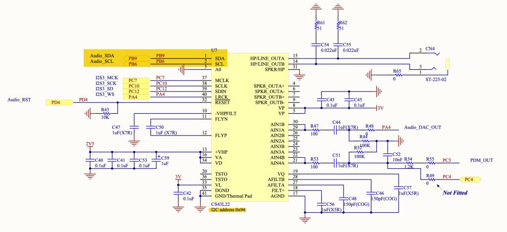
Now, create new source and header file with name of i2c.c and i2c.h respectively.
Within the header file:
#ifndef I2C_H_
#define I2C_H_


#include "stm32f4xx.h"                  // Device header
#include "delay.h"
#include "stdint.h"


void i2c_init(void);
char i2c_readByte(char saddr,char maddr,char *data);
void i2c_writeByte(char saddr,char maddr,char data);
void i2c_WriteMulti(char saddr,char maddr,char *buffer, uint8_t length);
void i2c_ReadMulti(char saddr,char maddr, int n, char* data);


#endif
Within the source file:
#include "i2c.h"

uint8_t inited=0;

void i2c_init(void)
{
	#define I2C1_AF 0x04

	if(inited==0)
	{
		RCC->AHB1ENR|=RCC_AHB1ENR_GPIOBEN; //enable gpiob clock
		RCC->APB1ENR|=RCC_APB1ENR_I2C1EN; //enable i2c1 clock

		//set PB6 and PB9 to alternative function
		GPIOB->MODER|=GPIO_MODER_MODE6_1|GPIO_MODER_MODE9_1;
		GPIOB->MODER&=~(GPIO_MODER_MODE6_0|GPIO_MODER_MODE9_0);

		GPIOB->AFR[0]|=(I2C1_AF<<GPIO_AFRL_AFSEL6_Pos);

		GPIOB->AFR[1]|=(I2C1_AF<<GPIO_AFRH_AFSEL9_Pos);

		GPIOB->OTYPER|=GPIO_OTYPER_OT6|GPIO_OTYPER_OT9; //set pb8 and pb9 as open drain

		I2C1->CR1=I2C_CR1_SWRST;

		I2C1->CR1&=~I2C_CR1_SWRST;

		I2C1->CR2|=50;

		I2C1->CCR=0xd2;

		I2C1->TRISE=0x2b; //output max rise

		I2C1->CR1|=I2C_CR1_PE;

		inited=1;
	}
}
char i2c_readByte(char saddr,char maddr, char *data)
{


	while(I2C1->SR2&I2C_SR2_BUSY){;}
	I2C1->CR1|=I2C_CR1_START;
	while(!(I2C1->SR1&I2C_SR1_SB)){;}
	I2C1->DR=saddr<<1;
	while(!(I2C1->SR1&I2C_SR1_ADDR)){;}
	(void)I2C1->SR2;
	while(!(I2C1->SR1&I2C_SR1_TXE)){;}
	I2C1->DR=maddr;
	while(!(I2C1->SR1&I2C_SR1_TXE)){;}
	I2C1->CR1|=I2C_CR1_START;
	while(!(I2C1->SR1&I2C_SR1_SB)){;}
	I2C1->DR=saddr<<1|1;
	while(!(I2C1->SR1&I2C_SR1_ADDR)){;}
	I2C1->CR1&=~I2C_CR1_ACK;
	(void)I2C1->SR2;
	I2C1->CR1|=I2C_CR1_STOP;
	while(!(I2C1->SR1&I2C_SR1_RXNE)){;}
	*data++=I2C1->DR;
	return 0;
}

void i2c_writeByte(char saddr,char maddr,char data)
{


	while(I2C1->SR2&I2C_SR2_BUSY){;}          /*wait until bus not busy*/
	I2C1->CR1|=I2C_CR1_START;                 /*generate start*/
	while(!(I2C1->SR1&I2C_SR1_SB)){;}         /*wait until start bit is set*/
	I2C1->DR = saddr<< 1;                 	 /* Send slave address*/
	while(!(I2C1->SR1&I2C_SR1_ADDR)){;}      /*wait until address flag is set*/
	(void)I2C1->SR2; 											 /*clear SR2 by reading it */
	while(!(I2C1->SR1&I2C_SR1_TXE)){;}       /*Wait until Data register empty*/
	I2C1->DR = maddr;                        /* send memory address*/
	while(!(I2C1->SR1&I2C_SR1_TXE)){;}       /*wait until data register empty*/
	I2C1->DR = data;
	while (!(I2C1->SR1 & I2C_SR1_BTF));      /*wait until transfer finished*/
	I2C1->CR1 |=I2C_CR1_STOP;								 /*Generate Stop*/

}

void i2c_WriteMulti(char saddr,char maddr,char *buffer, uint8_t length)
{

	while (I2C1->SR2 & I2C_SR2_BUSY);           //wait until bus not busy
	I2C1->CR1 |= I2C_CR1_START;                   //generate start
	while (!(I2C1->SR1 & I2C_SR1_SB)){;}					//wait until start is generated
	I2C1->DR = saddr<< 1;                 	 			// Send slave address
	while (!(I2C1->SR1 & I2C_SR1_ADDR)){;}        //wait until address flag is set
	(void) I2C1->SR2; 						      //Clear SR2
	while (!(I2C1->SR1 & I2C_SR1_TXE));           //Wait until Data register empty
	I2C1->DR = maddr;                      				// send memory address
	while (!(I2C1->SR1 & I2C_SR1_TXE));           //wait until data register empty
	//sending the data
	for (uint8_t i=0;i<length;i++)
	 {
	 I2C1->DR=buffer[i]; 													//filling buffer with command or data
		while (!(I2C1->SR1 & I2C_SR1_BTF));
	 }

	I2C1->CR1 |= I2C_CR1_STOP;										//wait until transfer finished
}


void i2c_ReadMulti(char saddr,char maddr, int n, char* data)
{

	while (I2C1->SR2 & I2C_SR2_BUSY){;}
	I2C1->CR1|=I2C_CR1_START;
	while(!(I2C1->SR1 & I2C_SR1_SB)){;}
	I2C1->DR=saddr<<1;
	while(!(I2C1->SR1 & I2C_SR1_ADDR)){;}
	(void)I2C1->SR2;
	while(!(I2C1->SR1&I2C_SR1_TXE)){;}
	I2C1->DR = maddr;
	while(!(I2C1->SR1&I2C_SR1_TXE)){;}
	I2C1->CR1|=I2C_CR1_START;
	while(!(I2C1->SR1 & I2C_SR1_SB)){;}
	I2C1->DR=saddr<<1|1;
	while(!(I2C1->SR1 & I2C_SR1_ADDR)){;}
	(void)I2C1->SR2;
	I2C1->CR1|=I2C_CR1_ACK;
	while(n>0U)
		{
		if(n==1U)
				{
				I2C1->CR1&=~I2C_CR1_ACK;
					I2C1->CR1|=I2C_CR1_STOP;
					while(!(I2C1->SR1&I2C_SR1_RXNE)){;}
					*data++=I2C1->DR;
						break;
				}
			else
					{

					while(!(I2C1->SR1&I2C_SR1_RXNE)){;}
						(*data++)=I2C1->DR;
							n--;
				}
}
}
Next part, we shall configure the I2S and start generating the clocks and send some data over I2S bus.
Stay tuned.
Happy coding 😉
Add Comment