In the previous guide (here), we took at the interrupt driven ADC. Now, we shall use DMA to acquire the data from multiple channels of the ADC.
In this guide, we shall cover the following:
- Why DMA with ADC in multichannel.
- Driver development.
- Results.
1. Why DMA with ADC Multichannel:
DMA which stands for Direct Memory Access is part of MCU that handle data transfer from peripheral to memory without invoking CPU at all which relief cpu to do something else, like processing the acquired adc vlaue for dsp processing etc
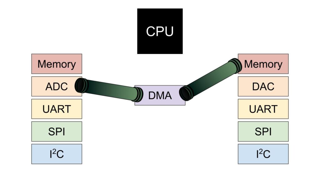
DMA can be operate in three different mode, Memory to Memory (moving one variable from one location to another), memory to peripheral (send string from memory to PC through UART) and peripheral to memory like in our case acquiring data from adc.
Why should we use DMA when dealing with multiple channel in ADC
Let say you want ti acquire data from adc from 3-channel in continuous mode. Since each conversion requires 15 cycles for 12-bit since the adc clock is the core frequency over (16MHz/2=8MHz), thats means generating interrupts at rate near half mega hertz which will effect the performance of the mcu. Hence, using DMA in such case makes sense.
2. Driver Development:
We start off by creating new project with name of ADC_DMA.
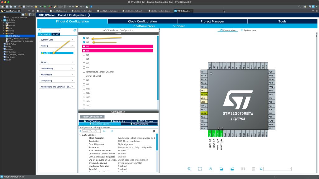
From pinout and configuration, select analog and select ADC. After that, enable IN0 and IN1 as following:
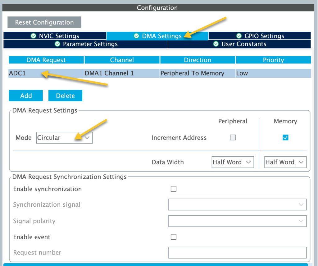
From DMA tab, enable the DMA for the ADC and set the mode to circular mode as following:
Set the ADC parameter as following:
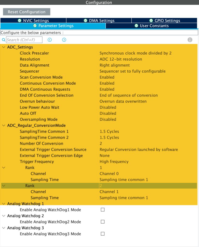
- First set number of conversion to 2.
- Enable continuous conversion mode.
- Enable DMA continuous request.
- In Rank 1, set the channel to be channel0.
- In Rank 2. set the channel to be channel1.
Last, enable the UART to transmit data. Check this guide.
Save the project and this will generate the code.
In main.c:
In DMA1_Init:
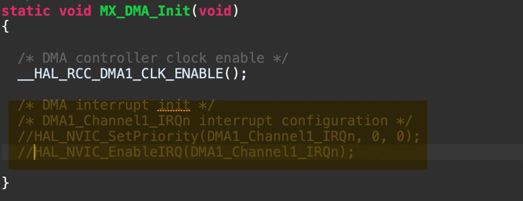
Disable the interrupt for the DMA since this will generate the interrupt so frequently that will spend the MCU processing the interrupt requests.
After disabling the DMA interrupt, in user code begin includes, include the stdio library as following:
#include "stdio.h"
In user code begin PV, declare an array with size of 2 which represent number of the ADC channels as following:
uint16_t adc_data[2];
In user code begin 0, we shall retarget the printf to print directly to the serial terminal as following:
int __io_putchar(int ch)
{
	HAL_UART_Transmit(&huart2, &ch, 1, 10);
	return ch;
}
In user code begin 2, we shall start the ADC with the DMA as following:
HAL_ADC_Start_DMA(&hadc1, (uint32_t)&adc_data, 2);
The function will take three parameters as following:
- handle to the ADC.
- Buffer to store the ADC data.
- Size of the data to be transferred.
In while 1 loop, user code begin 3:
Print the ADC data as following:
	  printf("ADC CH0=%d ADC CH1=%d \r\n",adc_data[0],adc_data[1]);
	  HAL_Delay(200);
Save the project, build it and run it on your STM32G070.
3. Results:
Open your favourite serial terminal and select the appropriate COM port and set the baudrate of 115200 and you should get the following:

In this case, CH0 is connected to ground and CH1 and to 3v3.
Happy coding 🙂
Add Comment