Injected channels in STM32 ADC provide a high-priority conversion mechanism that interrupts regular ADC conversions to perform critical measurements instantly. They are ideal for applications requiring precisely timed sampling, such as motor control or synchronized current sensing.
In this guide, we shall cover the following:
- Introduction.
- STM32CubeIDE setup.
- Firmware development.
- Results.
1. Introduction:
The Analog-to-Digital Converter (ADC) peripheral in STM32 microcontrollers provides two main types of conversion groups: regular and injected channels. While regular channels are used for standard, periodic, or continuous sampling of analog signals, injected channels are designed for time-critical measurements that require immediate conversion regardless of ongoing ADC operations. This functionality is particularly essential in applications such as motor control, where precise timing of current or voltage sensing relative to PWM cycles is critical for accurate control algorithms like Field-Oriented Control (FOC).
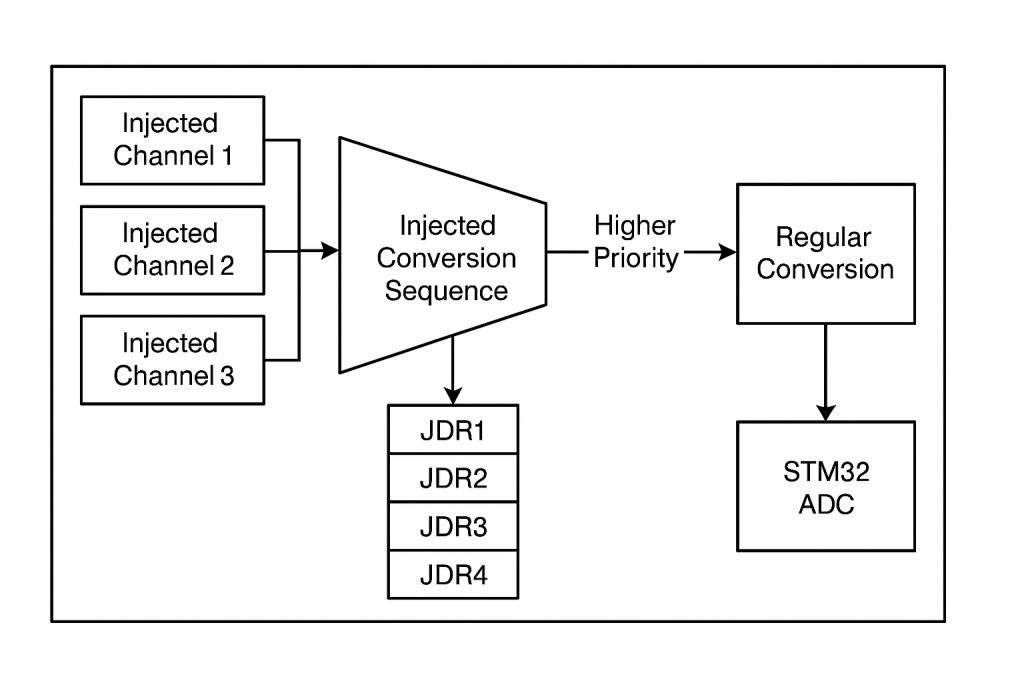
Injected channels operate by interrupting or preempting the regular conversion sequence to perform their conversion task as soon as they are triggered. This “injection” mechanism ensures minimal latency between the trigger event (typically a timer output compare or external interrupt) and the sampling instant. Once the injected conversion is completed, the ADC resumes its regular sequence seamlessly without user intervention. This preemption is handled entirely by the ADC hardware, ensuring deterministic response times crucial in control systems.
Each injected channel sequence can include up to four ranks, allowing multiple critical signals to be sampled back-to-back within the injected conversion group. The results of these conversions are stored in dedicated data registers called Injected Data Registers (JDR1–JDR4), separate from the regular Data Register (DR). This separation avoids data overwrite issues and simplifies the retrieval of injected conversion results without interfering with regular data streams.
The injected channels can be configured to operate on software triggers or hardware triggers. Hardware triggering is the most common use case, typically sourced from timer events synchronized with other control system timings. This is especially important in motor control, power inverters, and synchronized current measurements where conversion must occur at specific electrical phase angles to calculate instantaneous torque or power accurately.
In terms of sampling configurations, injected channels possess their own independent settings for sampling time, trigger sources, and sequence ranks. This independence ensures that while regular channels might be configured for high-speed conversions with minimal sampling time, injected channels can have optimized sampling durations to accommodate the impedance characteristics of the sensed signals. Moreover, the injected conversion can be configured to automatically start after a regular conversion, or it can preempt at any point when a trigger is detected, depending on the ADC’s configuration for discontinuous or automatic injection modes.
Internally, the STM32 ADC’s priority arbitration ensures injected conversions have the highest priority, followed by regular conversions, and finally any calibration or self-test routines. This guarantees that injected conversions are never delayed by ongoing regular conversions, which is a crucial design consideration in real-time control systems.
Finally, the injected channels support features such as offset correction (hardware subtraction of a programmed offset value from the conversion result), which is particularly useful in current shunt measurements where the shunt amplifier may have a non-zero offset voltage. The results are directly adjusted before storage in the JDR registers, minimizing CPU post-processing.
2. STM32CubeIDE Setup:
Open STM32CubeIDE after selecting the workspace and create new project as following:

Select the MCU:

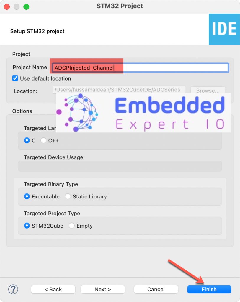
Give the project a name and click on finish:
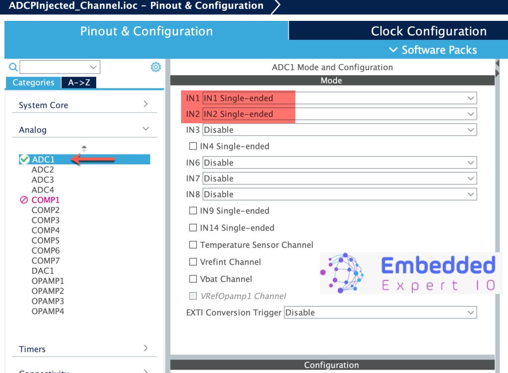
Once the project is created, from the left side window, select ADC:
- Enable IN1 and IN2 as single ended not differential (Not all STM32s have this feature)
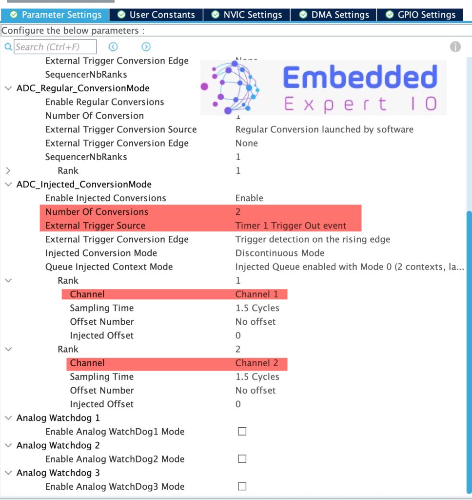
Next, from Parameters Settings:
In ADC Injection conversion mode:
- Set number of conversions to 2.
- External Trigger source to TIM1 Trigger Out Event.
- Set Rank 1 to channel1 and Rank 2 to channel 2
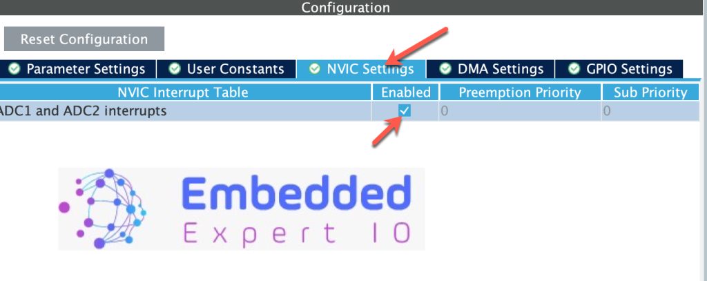
Next, enable NVIC for the ADC as follows:
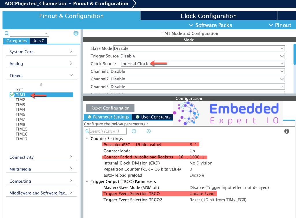
Next, configure TIM1 as follows:
- Clock source to Internal Clock.
- Prescaller to 8-1 (F303 runs at 8MHz).
- Counter Period to 1000-1.
- Trigger Even to Update Event.
Thats all for the STM32CubeIDE setup. Save the project project and this will generate the code.
3. Firmware Development:
Once the project is generated, main.c will be opened.
In main.c:
In user code begin PV, declare the following array:
uint16_t ADC_INJ_VAL[2];
Since the injection channels shall work in interrupt, we shall handle it in the interrupt as follows:
void HAL_ADCEx_InjectedConvCpltCallback(ADC_HandleTypeDef *hadc)
{
	if(hadc->Instance==ADC1)
	{
		ADC_INJ_VAL[0] = HAL_ADCEx_InjectedGetValue(hadc, ADC_INJECTED_RANK_1);
		ADC_INJ_VAL[1] = HAL_ADCEx_InjectedGetValue(hadc, ADC_INJECTED_RANK_2);
	}

}
The function:
HAL_ADCEx_InjectedConvCpltCallback(ADC_HandleTypeDef *hadc)
Will be called after the injection channels have completed the conversion.
Within the interrupt, first, check if the interrupt from ADC1 as follows:
if(hadc->Instance==ADC1)
If it is, store the measured injection channels as follow:
ADC_INJ_VAL[0] = HAL_ADCEx_InjectedGetValue(hadc, ADC_INJECTED_RANK_1);
ADC_INJ_VAL[1] = HAL_ADCEx_InjectedGetValue(hadc, ADC_INJECTED_RANK_2);
In user code begin2 in main function, start the timer in base mode and start the injection channels in interrupt mode as follows:
HAL_TIM_Base_Start(&htim1);
HAL_ADCEx_InjectedStart_IT(&hadc1);
Thats all for the firmware.
Build the project and run it.

4. Results:
In the debugging session, add ADC_INJ_VAL to live expression and you should get the following:
Happy coding 😉
Add Comment