Timer encoder mode in STM32 microcontrollers allows direct interfacing with quadrature encoders to measure position, speed, and direction without complex software decoding. By leveraging the timer’s hardware decoding capabilities, embedded systems can achieve accurate real-time rotary position tracking with minimal CPU load, making it ideal for motor control and precise motion applications.
In this guide, we shall cover the following:
- Introduction.
- STM32CubeIDE setup.
- Hardware setup.
- Firmware development.
- Results.
1.1 Introduction:
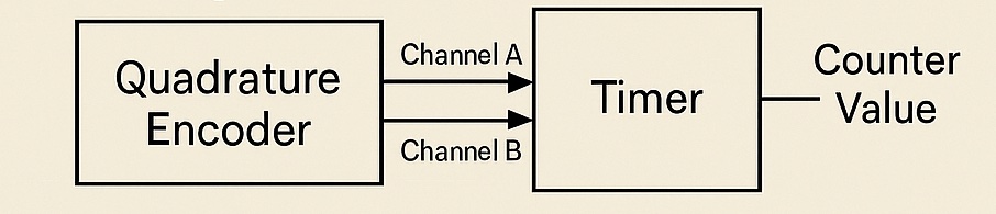
Timer encoder mode is a powerful feature available in STM32 microcontrollers that enables seamless and efficient interfacing with quadrature encoders for precise measurement of rotational position, direction, and speed. Quadrature encoders are widely used in motor control, robotics, CNC machines, automation systems, and instrumentation to provide accurate feedback on the movement and positioning of mechanical shafts or linear actuators. These encoders output two square wave signals, typically labeled Channel A and Channel B, which are phase-shifted by 90 degrees. By decoding these signals, it is possible to determine both the amount of movement and the direction of rotation.
Traditionally, decoding quadrature encoder signals requires implementing software algorithms that continuously monitor the two input channels, detect edges, and calculate position increments or decrements accordingly. However, this approach demands significant CPU resources, particularly when dealing with high-resolution encoders operating at high rotational speeds, which may generate tens or hundreds of thousands of pulses per second. Missing pulses due to interrupt latency or heavy processing loads can lead to critical inaccuracies in motion tracking or control systems.
STM32 timers with encoder interface mode overcome these challenges by handling quadrature decoding entirely in hardware. When configured in encoder mode, the timer uses its internal circuitry to process the two encoder channels (TI1 and TI2 inputs) and automatically updates the counter register based on the detected direction and number of pulses. This offloads the CPU from real-time pulse decoding, enabling fast and accurate position tracking even under demanding operating conditions. The timer’s counter will increment when the encoder rotates in one direction and decrement when it rotates in the opposite direction, giving a direct hardware representation of position relative to a zero reference.
Another significant advantage of timer encoder mode is its ability to operate seamlessly with minimal additional configuration. It includes selectable encoder resolution modes, allowing the counter to increment on rising edges only, both rising and falling edges of one channel, or on all edges of both channels (x1, x2, or x4 decoding). This increases effective resolution without requiring a higher-resolution physical encoder. Additionally, STM32 timers support programmable digital filters on encoder inputs to suppress noise and debounce mechanical jitter, enhancing signal integrity in industrial environments prone to electrical noise.
For applications that require absolute positioning, the encoder count can be reset to zero at startup or upon receiving an external index pulse. For incremental applications, the current count can be read periodically to determine position change or calculate speed by measuring counts over fixed time intervals. Moreover, with STM32’s high-speed timers, encoder mode supports counting frequencies sufficient for even the fastest motors used in robotics or precision motion control.
In summary, using timer encoder mode in STM32 simplifies quadrature signal decoding, improves measurement reliability, reduces CPU load, and enhances the performance of embedded systems requiring accurate motion tracking. It is an essential feature in advanced embedded motor drives, precision linear stages, and automation controllers where precise and efficient rotary position feedback is critical. The following sections will focus on the detailed software configuration, initialization, and data acquisition for implementing encoder mode in STM32 projects.
A rotary encoder, also called a shaft encoder, is an electro-mechanical device that converts the angular position or motion of a shaft or axle to analog or digital output signals.
Rotary encoders are used in a wide range of applications that require monitoring or control, or both, of mechanical systems, including industrial controls, robotics, photographic lenses, computer input devices such as optomechanical mice and trackballs, controlled stress rheometers, and rotating radar platforms.
1.2 Encoder types:
- Mechanical: Also known as conductive encoders. A series of circumferential copper tracks etched onto a PCB is used to encode the information via contact brushes sensing the conductive areas. Mechanical encoders areeconomical but susceptible to mechanical wear. They are common in human interfaces such as digital multimeters
- Optical: This uses a light shining onto a photodiode through slits in a metal or glass disc. Reflective versions also exist. This is one of the most common technologies. Optical encoders are very sensitive to dust.
- On-Axis Magnetic: This technology typically uses a specially magnetized 2 pole neodymium magnet attached to the motor shaft. Because it can be fixed to the end of the shaft, it can work with motors that only have 1 shaft extending out of the motor body. The accuracy can vary from a few degrees to under 1 degree. Resolutions can be as low as 1 degree or as high as 0.09 degree (4000 CPR, Count per Revolution). Poorly designed internal interpolation can cause output jitter, but this can be overcome with internal sample averaging.
- Off-Axis Magnetic: This technology typically employs the use of rubber bonded ferrite magnets attached to a metal hub. This offers flexibility in design and low cost for custom applications. Due to the flexibility in many off axis encoder chips they can be programmed to accept any number of pole widths so the chip can be placed in any position required for the application. Magnetic encoders operate in harsh environments where optical encoders would fail to work. (from wikipedia)
1.3 Encoder Output:
In out case, the encoder shall generate pulses on both DT and CLK lines in a certain manner that can be read by the timer of stm32. In the figure below, is the output from shaft encoder when rotating clockwise. Clk is yellow and DT is Blue.
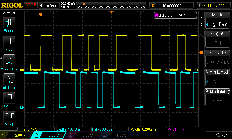
When the shaft encoder rotate clockwise, CLK like pulled high first then DT line which indicates there is rotation.
When the counter clock rotation occurs, the DT line is pulled high first then the CLK line.

2. STM32CubeIDE Setup:
Open STM32CubeIDE after selecting the workspace and create new project as following:

Select the MCU:

Give the project a name:
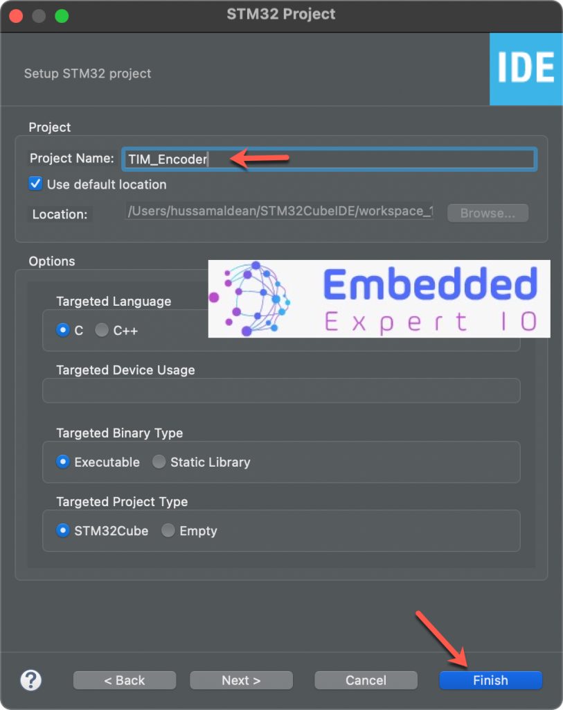
Click on Finish.
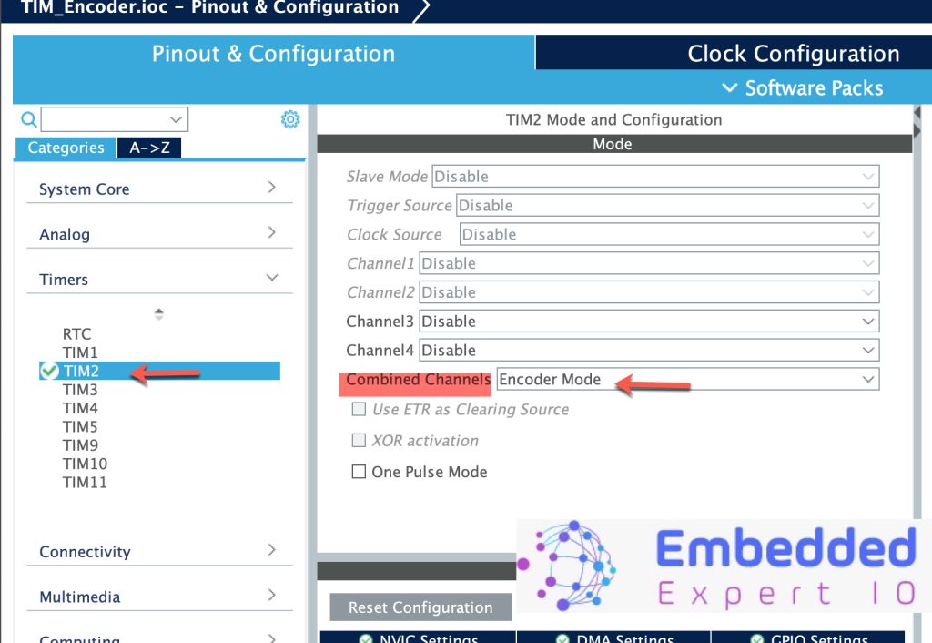
Next, STM32CubeMX window will appear, from timer configure TIM2 as follows:
- Select TIM2 then Combined Channels, set it to Encoder Mode.
Next, in timer configuration:
- Set Counter Period to be encoder output pulses per rotation by 4 (360*4=1440).
- Encoder Mode to TI1 and TI2.
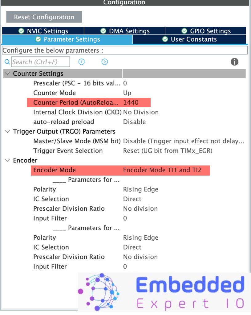
Keep the rest as default.
Save the project and this will generate the code.
3. Hardware Setup:
The setup as follows:
The connection is as following
| Encoder Pin | STM32F411-Nucleo64 Pin |
| GND | GND |
| + | 3V3 |
| DT | PA0 |
| CLK | PA1 |
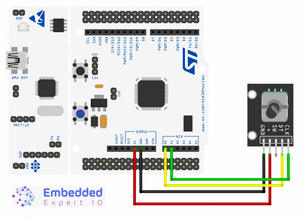
4. Firmware Development:
Once the project has been generated, the main.c shall be opened.
In user code begin PV, declare the following variables:
uint16_t EncoderVal;
uint8_t EncoderDir;
- EncoderVal shall hold the current encoder count.
- EncoderDir shall hold the rotation direction, clockwise or counterclockwise.
Next, in user code begin 2 in main function:
Start the timer in encoder mode as follows
HAL_TIM_Encoder_Start(&htim2, TIM_CHANNEL_ALL);
In user code begin 3 in while 1 loop:
EncoderVal=__HAL_TIM_GET_COUNTER(&htim2);
EncoderDir=__HAL_TIM_IS_TIM_COUNTING_DOWN(&htim2);
The following:
EncoderVal=__HAL_TIM_GET_COUNTER(&htim2);
This will read the current timer counter which is the current encoder output multiplied by 4.
And the line:
EncoderDir=__HAL_TIM_IS_TIM_COUNTING_DOWN(&htim2);
This will indicate the rotation direction, 0 is the desired direction (e.g. clockwise) and 1 is the opposite direction (e.g. counterclockwise).
Build the project and run it.

5. Results:
In the debugging session, add EncoderVal and EncoderDir to live expression and you should get the following:

If you added interrupt and calculate the time between each interrupt, you will be able to measure the RPM. Feel free to implement this as task for you.
Happy coding 😉
Add Comment