In this guide, we shall take a look at the timers in STM32G070 and implement timer driver to blink an LED using hardware level without any software delay etc.
In this guide, we shall cover the following:
- Timer features in STM32G070.
- What is Output compare mode.
- Developing the driver.
- LED Connection.
- Results.
1. Timer Features in STM32G070:
The general-purpose timers consist of a 16-bit auto-reload counter driven by a programmable prescaler.
General-purpose TIMx timer features include:
• 16-bit TIM3, TIM4 (a) up, down, up/down auto-reload counter.
• 16-bit programmable prescaler used to divide (also “on the fly”) the counter clock frequency by any factor between 1 and 65535.
• Up to 4 independent channels for:
– Input capture
– Output compare
– PWM generation (Edge- and Center-aligned modes)
– One-pulse mode output
• Synchronization circuit to control the timer with external signals and to interconnect several timers.
• Interrupt/DMA generation on the following events:
– Update: counter overflow/underflow, counter initialization (by software or internal/external trigger)
– Trigger event (counter start, stop, initialization or count by internal/external trigger)
– Input capture
– Output compare
• Supports incremental (quadrature) encoder and hall-sensor circuitry for positioning purposes
• Trigger input for external clock or cycle-by-cycle current management.

2. Output Compare Mode:
In STM32 microcontrollers, the Output Compare (OC) mode in the timer peripheral allows you to generate a waveform with a predefined period and pulse width. This mode is often used for generating PWM (Pulse Width Modulation) signals, generating timing signals for controlling peripherals, or triggering events.
In OC mode, the timer’s counter value is compared to a predefined value called the compare value. When the counter matches the compare value, an action can be taken, such as toggling an output pin, setting it high or low, or triggering an interrupt. In our case, we shall toggle a pin connected to the timer.

3. Developing the Driver:
Before heading into driver developing, please refer to this guide for how to start a new project using HAL within STM32CubeIDE.
After creating new project with name of TIM_Output_Compare. open clock configuration tab as following:
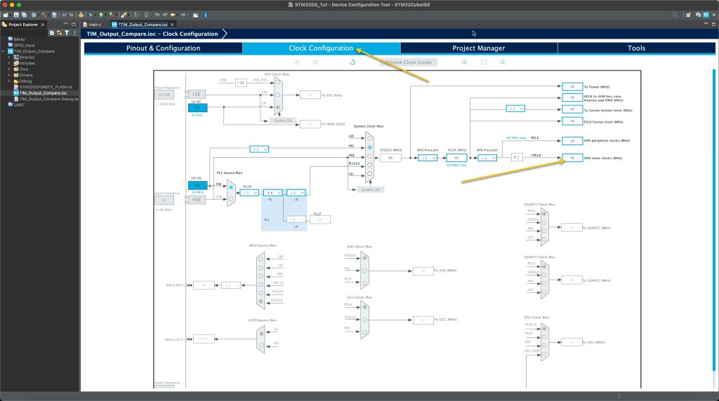
Notice the value of APB Timer clocks which is 16MHz in this case.
Now, from Pinout and Configuration tab, enable timer 3:
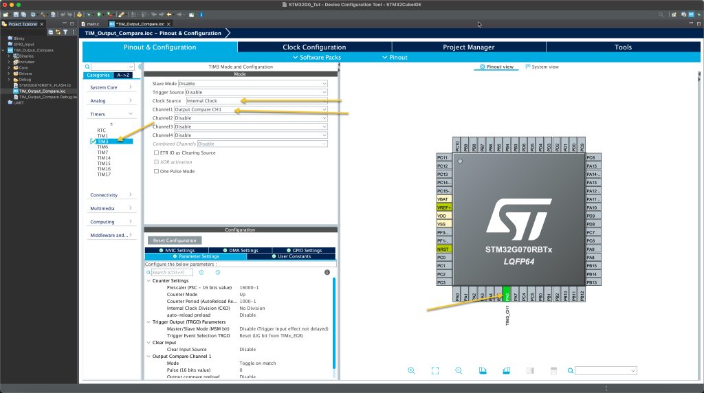
Set the clock source to be internal, Set channel 1 to be output compare CH1 and you will notice CubeMX already set PA6 to work with timer3 in output compare mode.
Now, we need to configure the timer.
First we need to set the required prescaller and counter period.
Since the timer clock is 16MHz and we need to get 1Hz, we shall use the following equation to determine the required frequency and period as following:

By setting the PSC to 15999 and ARR to 999, we get the desired frequency of 1Hz.
Hence, configure the timer as following:
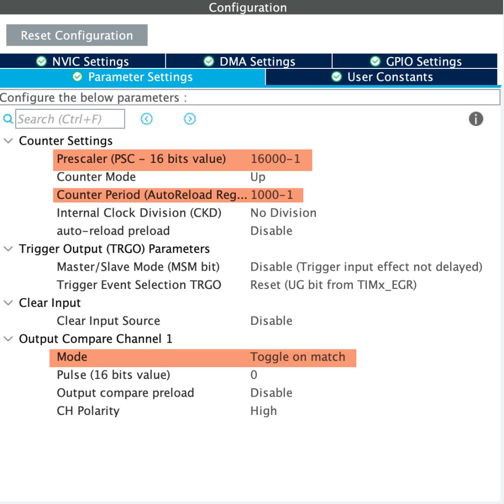
Also, set the output compare channel mode to be toggle on match which will toggle the pin when the Counter match the CCR value which is 0 in this case.
Save the project and this should generate the project.
In user begin code 2, add the following line:
HAL_TIM_OC_Start(&htim3, TIM_CHANNEL_1);
This function will start the channel in output compare mode and takes two arguments:
- Pointer to timer handler.
- the channel of the timer to be started.
It returns HAL_StatusTypedef:
- HAL_OK.
- HALL_ERROR.
- HAL_BUSY.
- HAL_TIMEOUT.
That all for the driver section, save the code and upload it to your MCU.
4. Connection:
The connection as following and you will need those extra componets:
- Breadboard.
- Hockup wires.
- LED (any color).
- 100Ohm resistor.
Connect the LED to MCU as shown below:

5. Results:
Once you uploaded the code, you should get the following:
Happy coding 🙂
Add Comment