In this guide series, we shall see how to develop external loader with combination of W25QXX to extend the size of the internal storage and store large data for your application.
In part 1, we shall cover the following:
- Brief introduction to external loader.
- Environment setup.
- System initialization function.
- Delay setup.
- W25QXX connection with STM32F4xx
- SPI setup.
- W25QXX header file.
- Project Setup download
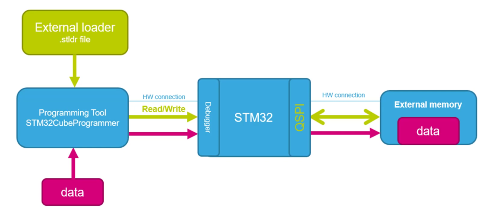
1. Brief introduction to external loader:
The STM32CubeProgrammer’s External Loader is a feature that allows a direct access to external memories by STM32CubeProgrammer and even by the STM32CubeIDE to read, program, and erase data without the use of any additional tool other than a regular STLINK and even without ever changing the internal flash memory of the STM32. It is a feasible way to accelerate the debug cycle and the manufacturing program process on applications that use external memory.
2. Environment Setup:
To setup the STM32CubeIDE for this guide series, take a look at this guide for how to obtain the header file, correct project setup etc.
3. System Initialization function:
Create new source file and name it with sys_init.c:
Within the source file, include the following header file:
#include "stm32f4xx.h"
Declare the following function:
void SystemInit (void)
This function will be called once the MCU is started. Hence, no need to call it from main.
Within the function:
- Enable float point uint.
- Enable cell compensation.
void SystemInit (void)
{

	/*Enable float point hardware*/
	SCB->CPACR |= ((3UL << 10*2)|(3UL << 11*2));

	/*Enable cell compensation*/
	RCC->APB2ENR|=RCC_APB2ENR_SYSCFGEN ;
	SYSCFG->CMPCR|=SYSCFG_CMPCR_CMP_PD;
	while(!((SYSCFG->CMPCR)&(SYSCFG_CMPCR_READY))){;}

}
4. Delay Setup:
Create new source and header file with name of delay.c and delay.h respectively:
Within the header file:
#ifndef __delay__H__
#define __delay__H__

#include "stdint.h"

/*
 * @brief This function will initialize SysTick
 * to generate 1ms interrupt.
 * @param freq source frequency of SysTick.
 * @return nothing.
 * @see Generic ARM CortexM4 user guide.
 * */

void delay_init(uint32_t freq);

/*
 * @brief This function will return the current millis.
 *
 * @param nothing.
 * @return current millis.
 * */
uint64_t millis();


/*
 * @brief This function will spin lock the CPU to delay for the required
 * amount
 * @param time to be delayed in milliseconds.
 * @return nothing.
 * */
void delay(uint32_t time);


#endif
Within the source file:
#include "delay.h"
#include "stm32f4xx.h"


#define	CTRL_ENABLE					(1U<<0) /*Enable SysTick Timer*/
#define CTRL_CLKSRC					(1U<<2) /*Clock source selection*/
#define CTRL_COUNTFLAG				(1U<<16) /*Count flag bit*/
#define CTRL_TICKINT				(1U<<1) /*Interrupt enable bit*/


volatile uint64_t mil; /*volatile variable to hold the ms counter*/

void delay_init(uint32_t freq)
{

	/*Set period to be 1ms*/
	SysTick->LOAD  = (freq/1000) - 1;

	/*Clear systick current value register */
	SysTick->VAL = 0;

	/*Enable systick and select internal clk src*/
	SysTick->CTRL = CTRL_ENABLE | CTRL_CLKSRC ;

	/*Enable systick interrupt*/
	SysTick->CTRL  |= CTRL_TICKINT;

}


uint64_t millis()
	{

	__disable_irq(); /*Disable global interrupt*/

	uint64_t ml=mil; /*Get the current millis values and store in ml*/

	__enable_irq(); /*Enable global interrupt*/

	return ml;		/*Return the stored value*/
	}


/*Spin lock the CPU to delay*/
void delay(uint32_t time)
{

	uint64_t start=millis();
	while((millis() - start) < (time+1));
}

/*Interrupt handler of SysTick*/
void SysTick_Handler(void)
{
	/*Increment the counter with every interrupt*/
	mil++;
}
5. Connection of W25QXX with STM32F4xx:
The connection as following:

| STM32F411-Nucleo64 | W25QXX |
| 3V3 | Vcc |
| GND | GND |
| PA0 | CS |
| PA5 | CLK |
| PA6 | DO |
| PA7 | DI |
6. SPI setup:
Create new source and header file with name of SPI1.c and SPI1.h respectively.
Within the header file:
#ifndef SPI1_H_
#define SPI1_H_

#include "stdint.h"


/*
 * @brief This function will initialize SPI1 related pins.
 * @return nothing.
 * @see Pinout of datasheet for SPI pins.
 * */
void SPI1_Pins_Init(void);


/*
 * @brief This function will initialize CS pin .
 * @return nothing.
 * */
void W25QXX_CS_Pins_Init(void);

/*
 * @brief This function will initialize SPI1
 * and configure it.
 * @return nothing.
 * @see reference manual SPI section.
 * */
void SPI1_Config(void);

/*
 * @brief This function will transmit data over SPI bus.
 * @param *data pointer to the data to be written.
 * @param size  size of the data to be written.
 * @return nothing.
 * */
void SPI1_Transmit(uint8_t *data,uint32_t size);

/*
 * @brief This function will read data from SPI bus.
 * @param *data pointer to the data to be read.
 * @param size  size of the data to be read.
 * @return nothing.
 * */
void SPI1_Receive(uint8_t *data,uint32_t size);

/*
 * @brief This function will set CS pin to Low .
 * @return nothing.
 * */
void W25QXX_CS_LOW(void);

/*
 * @brief This function will set CS pin to High.
 * @return nothing.
 * */
void W25QXX_CS_HIGH(void);

#endif /* SPI1_H_ */
For the source file:
#include <SPI1.h>
#include "stm32f4xx.h"


void SPI1_Pins_Init(void)
{
	RCC->AHB1ENR|=RCC_AHB1ENR_GPIOAEN; //enable clock for GPIOA
	GPIOA->MODER|=GPIO_MODER_MODE5_1|GPIO_MODER_MODE6_1|GPIO_MODER_MODE7_1; //set PA5, PA6 and PA7 to alternate function mode
	GPIOA->MODER &=~(GPIO_MODER_MODE5_0|GPIO_MODER_MODE6_0|GPIO_MODER_MODE7_0);

	GPIOA->OSPEEDR|=GPIO_OSPEEDER_OSPEEDR5|GPIO_OSPEEDER_OSPEEDR6|GPIO_OSPEEDER_OSPEEDR7;

	GPIOA->AFR[0]|=(0x05<<20)|(0x05<<24)|(0x05<<28);
}


void W25QXX_CS_Pins_Init(void)
{
	RCC->AHB1ENR|=RCC_AHB1ENR_GPIOAEN; //enable clock for GPIOA
	/*Set PA0 as output*/
	GPIOA->MODER|=GPIO_MODER_MODE0_0;
	GPIOA->MODER&=~GPIO_MODER_MODE0_1;

	/*Set pin high as initial state*/
	GPIOA->BSRR =GPIO_BSRR_BS0;
}


void SPI1_Config(void)
{
	/*Enable clock access to SPI1 module*/
	RCC->APB2ENR |= RCC_APB2ENR_SPI1EN;

	/*Set clock to fPCLK/2*/
	SPI1->CR1 &=~SPI_CR1_BR_0;
	SPI1->CR1 &=~SPI_CR1_BR_1;
	SPI1->CR1 &=~SPI_CR1_BR_2;

	/*Set CPOL to 0 and CPHA to 0 (MODE0)*/
	SPI1->CR1 &=~(SPI_CR1_CPOL);
	SPI1->CR1 &=~(SPI_CR1_CPHA);

	/*Enable full duplex*/
	SPI1->CR1 &=~(SPI_CR1_RXONLY);

	/*Set MSB first*/
	SPI1->CR1 &= ~(SPI_CR1_LSBFIRST);

	/*Set mode to MASTER*/
	SPI1->CR1 |= (SPI_CR1_MSTR);

	/*Set 8 bit data mode*/
	SPI1->CR1 &= ~(SPI_CR1_DFF);

	/*Select software slave management by
	* setting SSM=1 and SSI=1*/
	SPI1->CR1 |= (SPI_CR1_SSM);
	SPI1->CR1 |= (SPI_CR1_SSI);

	/*Enable SPI module*/
	SPI1->CR1 |= (SPI_CR1_SPE);
}

void SPI1_Transmit(uint8_t *data,uint32_t size)
{
	uint32_t i=0;

	while(i<size)
	{
		/*Wait until TXE is set*/
		while(!(SPI1->SR & (SPI_SR_TXE))){}

		/*Write the data to the data register*/
		SPI1->DR = data[i];
		i++;
	}
	/*Wait until TXE is set*/
	while(!(SPI1->SR & (SPI_SR_TXE))){}

	/*Wait for BUSY flag to reset*/
	while((SPI1->SR & (SPI_SR_BSY))){}

	/*Clear OVR flag*/
	(void)SPI1->DR;
	(void)SPI1->SR;
}

void SPI1_Receive(uint8_t *data,uint32_t size)
{
	while(size)
	{
		/*Send dummy data*/
		SPI1->DR =0;

		/*Wait for RXNE flag to be set*/
		while(!(SPI1->SR & (SPI_SR_RXNE))){}

		/*Read data from data register*/
		*data++ = (SPI1->DR);
		size--;
	}
}


void W25QXX_CS_LOW(void)
{
	GPIOA->BSRR =GPIO_BSRR_BR0;

}

/*Pull high to disable*/
void W25QXX_CS_HIGH(void)
{
	GPIOA->BSRR =GPIO_BSRR_BS0;
}
For more information, please refer to the following guide.
7. W25QXX header file.
Since the functions needed for the external loader need to be in specific format, we shall use the following format as shown in the header file:
#ifndef W25QXX_H_
#define W25QXX_H_

#define MEMORY_FLASH_SIZE				0x400000 /* 32Mbit =>4Mbyte */
#define MEMORY_BLOCK_SIZE				0x10000   /*  blocks of 64KBytes */
#define MEMORY_SECTOR_SIZE				0x1000    /* 4kBytes */
#define MEMORY_PAGE_SIZE				0x100     /* 256 bytes */

#define W25Q_WRITE_ENABLE 0x06
#define W25Q_WRITE_DISABLE 0x04

#define W25Q_READ_SR1 0x05
#define W25Q_READ_SR2 0x35
#define W25Q_READ_SR3 0x15
#define W25Q_WRITE_SR1 0x01
#define W25Q_WRITE_SR2 0x31
#define W25Q_WRITE_SR3 0x11

#define W25Q_READ_DATA 0x03
#define W25Q_READ_DATA_4B 0x13
#define W25Q_FAST_READ 0x0B
#define W25Q_FAST_READ_4B 0x0C

#define W25Q_PAGE_PROGRAM 0x02
#define W25Q_PAGE_PROGRAM_4B 0x12

#define W25Q_SECTOR_ERASE 0x20
#define W25Q_SECTOR_ERASE_4B 0x21
#define W25Q_32KB_BLOCK_ERASE 0x52
#define W25Q_64KB_BLOCK_ERASE 0xD8
#define W25Q_64KB_BLOCK_ERASE_4B 0xDC
#define W25Q_CHIP_ERASE 0xC7

#define W25Q_ENABLE_RST 0x66
#define W25Q_RESET 0x99

void W25Q_Reset (void);
void W25Q_Chip_Erase (void);
uint32_t W25Q_ReadID (void);

void W25Q_Read (uint32_t startPage, uint8_t offset, uint32_t size, uint8_t *rData);
void W25Q_FastRead (uint32_t startPage, uint8_t offset, uint32_t size, uint8_t *rData);

void W25Q_Erase_Sector (uint16_t numsector);

void W25Q_Write_Clean(uint32_t page, uint16_t offset, uint32_t size, uint8_t *data);
void W25Q_Write (uint32_t page, uint16_t offset, uint32_t size, uint8_t *data);

void W25Q_Write_Byte (uint32_t Addr, uint8_t data);
uint8_t W25Q_Read_Byte (uint32_t Addr);

float W25Q_Read_NUM (uint32_t page, uint16_t offset);
void W25Q_Write_NUM (uint32_t page, uint16_t offset, float data);

void W25Q_Read_32B (uint32_t page, uint16_t offset, uint32_t size, uint32_t *data);
void W25Q_Write_32B (uint32_t page, uint16_t offset, uint32_t size, uint32_t *data);


void flash_WriteMemory(uint8_t* buffer, uint32_t address, uint32_t buffer_size);
void flash_ReadMemory (uint32_t Addr, uint32_t Size, uint8_t* buffer);
void flash_SectorErase(uint32_t EraseStartAddress, uint32_t EraseEndAddress);
void flash_ChipErase (void);
void flash_Reset (void);

#endif /* W25QXX_H_ */
In part 2, we shall fill the source file of W25QXX.
8. Project setup download:
Stay tuned and happy coding 🙂
Add Comment