
In this guide, we shall see what is EEPROM and how to interface AT24C32 EEPROM with STM32F4xx. In part1, we shall cover the single byte read write operation to the eeprom.
In this guide, we shall cover the following:
- What is EEPROM.
- Features of AT24C32.
- AT24C32 Connection with STM32F4xx.
- Developing the Read function.
- Developing the write function.
- Main code.
- Code.
- Results.
1. What is EEPROM:
EEPROM stands for Electrically Erasable Programmable Read-Only Memory. To gain a better understanding of what these chips do, and what sort of applications EEPROM products are used for, it helps to break down the meaning of each word in its full name:
Electrically Erasable
- When connected to a power supply (PSU) via a motherboard or other suitable electronic circuit, the stored contents of EEPROM modules can be erased (deleted), either entirely or on an individual byte-per-section basis
Programmable
- PROM, or programmable ROM, indicates a module whose contents are intended to be written to memory after the chip has been installed into a system
- When attached to an appropriate circuit, for example as part of a desktop computer system, the application of electrical voltages to EEPROM chips allows users to modify or reprogramme the contents stored on the memory module
Read-Only
- Read-only memory (ROM and PROM) refers to modules designed for the long-term storage of information that does not change dynamically
- Non-dynamic data includes most types of user files, firmware, and some programs or code – elements that are not intended to receive regular automatic updates
- Like most ROM chips, EEPROM modules provide non-volatile functionality. This means any information stored on the chip can still be retrieved after a zero-power state, i.e. after the device or computer it is installed in has been turned off and back on again. This is not the case with RAM (Random Access Memory). RAM is designed for performing dynamic tasks rather than long-term information storage and is effectively wiped at the instant it reverts to a powered-off state
In simple terms, EEPROM is a type of memory module that can be used to hold, retrieve and delete information when installed in a computer or other electronic device. (source).
2. Features of AT24C32:
The features of AT32C32 as following:
• Low-Voltage and Standard-Voltage Operation
– 2.7 (V CC = 2.7V to 5.5V)
– 1.8 (V CC = 1.8V to 5.5V)
• Low-Power Devices (I SB = 2 µA at 5.5V) Available
• Internally Organized 4096 x 8, 8192 x 8
• 2-Wire Serial Interface
• Schmitt Trigger, Filtered Inputs for Noise Suppression
• Bidirectional Data Transfer Protocol
• 100 kHz (1.8V, 2.5V, 2.7V) and 400 kHz (5V) Clock Rate
• Write Protect Pin for Hardware Data Protection
• 32-Byte Page Write Mode (Partial Page Writes Allowed)
• Self-Timed Write Cycle (10 ms max)
• High Reliability
– Endurance: 1 Million Write Cycles
– Data Retention: 100 Years
The AT24C32/64 provides 32,768/65,536 bits of serial electrically erasable and programmable read only memory (EEPROM) organized as 4096/8192 words of 8 bits each. The device’s cascadable feature allows up to 8 devices to share a common 2wire bus. The device is optimized for use in many industrial and commercial applications where low power and low voltage operation are essential.
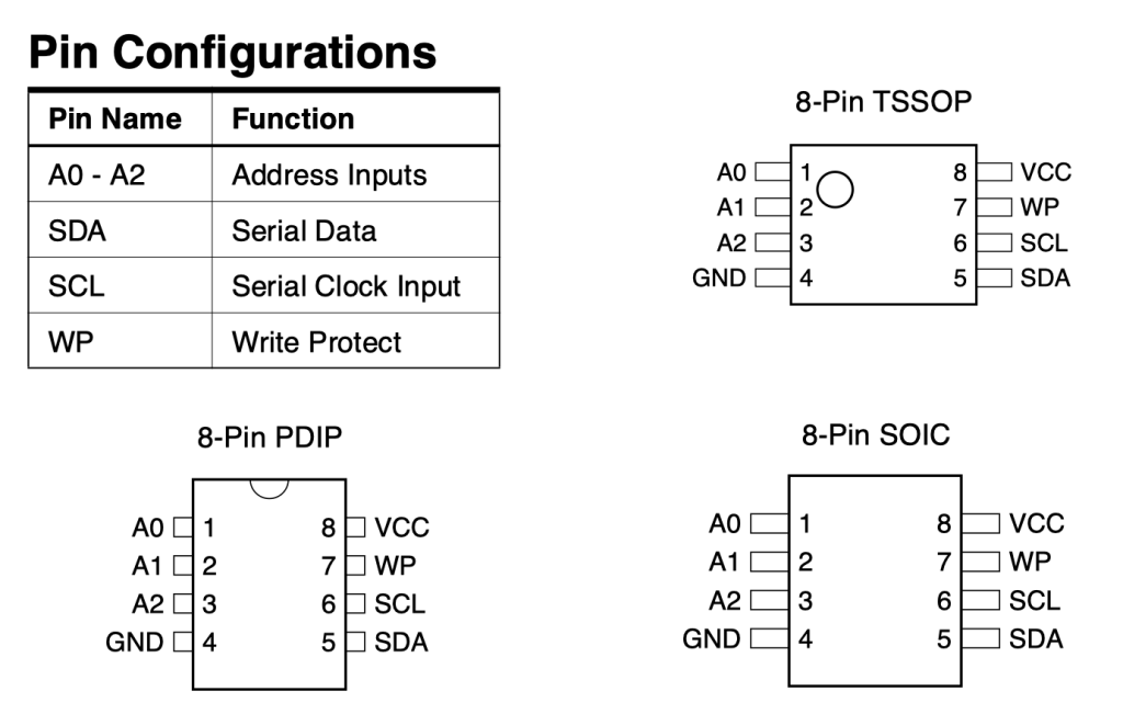
Pin Configurations:
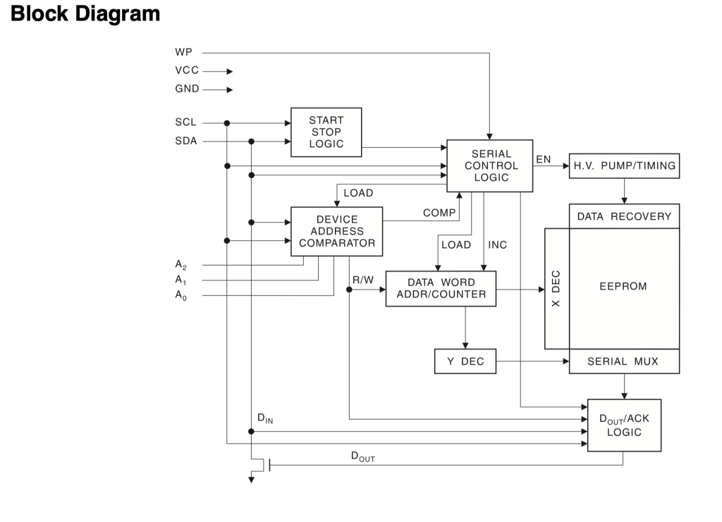
Block Diagram:
3. AT24C32 Connection with STM32F4xx:
Since the EEPROM came with the RTC3231 module, you can share the same i2c bus with EEPROM and RTC.
Hence, the connection as following:
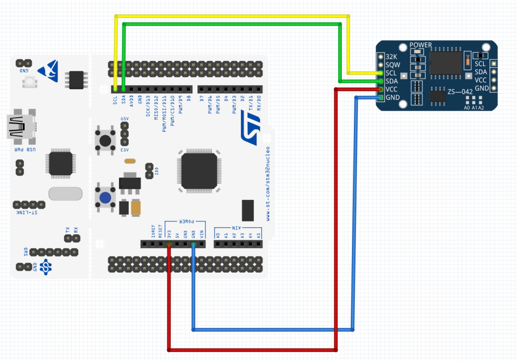
| STM32F411 Nucleo64 | AT24C32 |
| 5V | Vcc |
| GND | GND |
| PB8 | SCL (Pull to 5V with 4.7K) |
| PB9 | SDA (Pull to 5V with 4.7K) |
4. Developing the Read Function:
Before heading into developing the driver, take a look at this guide what is I2C and how to configure it.
To start off, create new header file with name of AT24C32.h
Within the header file, include the header guard:
#ifndef AT24C32_H_
#define AT24C32_H_


#endif /* AT24C32_H_ */
Include stdint library:
#include "stdint.h"
Declare the read function as following:
void AT24C32_ReadByte(uint16_t address, uint8_t *data);
The function takes the following two arguments:
- uint16_t to indicate which address to be read.
- Pointer to hold the data to be read.
For write function:
void AT24C32_WriteByte(uint16_t address, uint8_t data);
Takes similar parameters except that the data as value rather than pointer.
Now, create new source file with name of AT24C32.c
With in the source file, include the following:
#include "AT24C32.h"

#include "stm32f4xx.h"
Declare a macro that holds the address of the AT24C32, by default, it is 0x57.
#define AT24C32Address 0x57
For the read function, the steps as following:
- Check if the bus is busy and wait until it is free.
- Send start condition and wait until the start flag is set.
- Send the slave address with R/W bit set to 0 for write operation.
- Send the MSB of the address and wait until the TX buffer is empty.
- Send the LSB of the address and wait until the TX buffer is empty.
- Generate restart condition.
- Wait until the start flag is set.
- Send the slave address with R/W set to 1 to indicate read operation.
- Wait until the address flag is set.
- Disable acknowledgment.
- Generate stop condition and read back the DR register.
Since the EEPROM has 4096 address, we need to split the address to two bytes by sending the MSB first (bit 8 to 12/13) followed by the LSB (bit 0 to bit 7) as shown below:
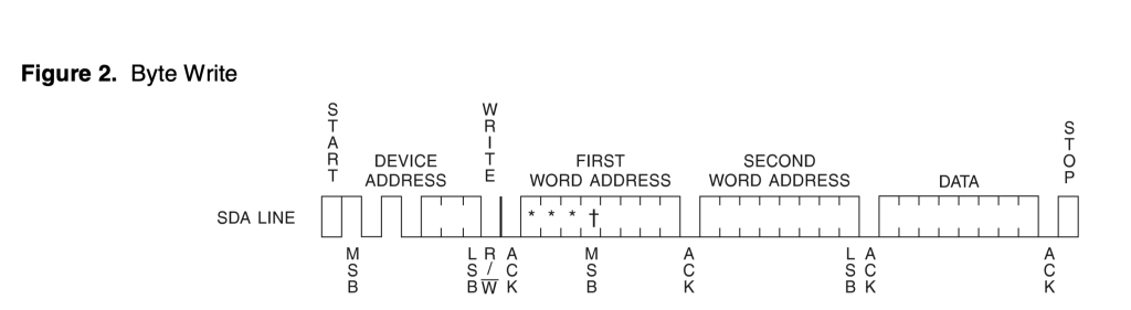
Hence, the byte read code as following:
void AT24C32_ReadByte(uint16_t address, uint8_t *data)
{
	while (I2C1->SR2 & I2C_SR2_BUSY);           //wait until bus not busy

	I2C1->CR1 |= I2C_CR1_START;                 //generate start

	while (!(I2C1->SR1 & I2C_SR1_SB)){;}	    //wait until start is generated

	I2C1->DR = AT24C32Address<< 1;              // Send slave address

	while (!(I2C1->SR1 & I2C_SR1_ADDR)){;}        //wait until address flag is set

	(void) I2C1->SR2; 						      //Clear SR2

	while (!(I2C1->SR1 & I2C_SR1_TXE));           //Wait until Data register empty

	I2C1->DR=address>>8;						//Send MSB of the address

	while(!(I2C1->SR1&I2C_SR1_TXE)){;}			//Wait until Data register empty

	I2C1->DR=address&0x0F;						// send LSB of the address

	while(!(I2C1->SR1&I2C_SR1_TXE)){;}			//Wait until Data register empty


	I2C1->CR1 |= I2C_CR1_START;                 //generate start

	while (!(I2C1->SR1 & I2C_SR1_SB)){;}	    //wait until start is generated

	I2C1->DR = (AT24C32Address<< 1)|1;          // Send slave address with read operation

	while(!(I2C1->SR1&I2C_SR1_ADDR)){;}			//Wait for address flag to set

	I2C1->CR1&=~I2C_CR1_ACK;					//Disable acknowledgment

	(void)I2C1->SR2;							// Clear SR2

	I2C1->CR1|=I2C_CR1_STOP;					// Generate stop condition

	while(!(I2C1->SR1&I2C_SR1_RXNE)){;}			//Wait for receiver buffer to be filled

	*data=I2C1->DR;								//Store the I2C bus.

}
5. Developing the Write Function:
It is similar to the read operation until the LSB address then:
- Send the data.
- Wait until the transfer has completed by checking BTF flag.
- Generate stop condition.
Hence, the write function as following:
void AT24C32_WriteByte(uint16_t address, uint8_t data)
{
	while (I2C1->SR2 & I2C_SR2_BUSY);           //wait until bus not busy

	I2C1->CR1 |= I2C_CR1_START;                 //generate start

	while (!(I2C1->SR1 & I2C_SR1_SB)){;}	    //wait until start is generated

	I2C1->DR = AT24C32Address<< 1;              // Send slave address

	while (!(I2C1->SR1 & I2C_SR1_ADDR)){;}        //wait until address flag is set

	(void) I2C1->SR2; 						      //Clear SR2

	while (!(I2C1->SR1 & I2C_SR1_TXE));           //Wait until Data register empty

	I2C1->DR=address>>8;						//Send MSB of the address

	while(!(I2C1->SR1&I2C_SR1_TXE)){;}			//Wait until Data register empty

	I2C1->DR=address&0x0F;						// send LSB of the address

	while(!(I2C1->SR1&I2C_SR1_TXE)){;}			//Wait until Data register empty

	I2C1->DR = data; 							//Write the data to the EEPROM

	while (!(I2C1->SR1 & I2C_SR1_BTF));      	//wait until transfer finished

	I2C1->CR1 |=I2C_CR1_STOP;					//Generate Stop

}
6. Main code.
In main.c:
#include "i2c.h"
#include "time_base.h"
#include "uart.h"
#include "stdio.h"
#include "AT24C32.h"

uint8_t data_read;

uint8_t data_write=20;

uint16_t address=100;


int main(void)
{
	Ticks_Init(16000000);

	uart2_rxtx_init();

	i2c_init();

	AT24C32_WriteByte(address,data_write);

	printf("Data written to address %d is %d \r\n",address,data_write);

	AT24C32_ReadByte(address,&data_read);

	printf("Data read from address %d is %d \r\n",address,data_read);


	while(1)
	{
	}

}
7. Code:
You may download the code from here:
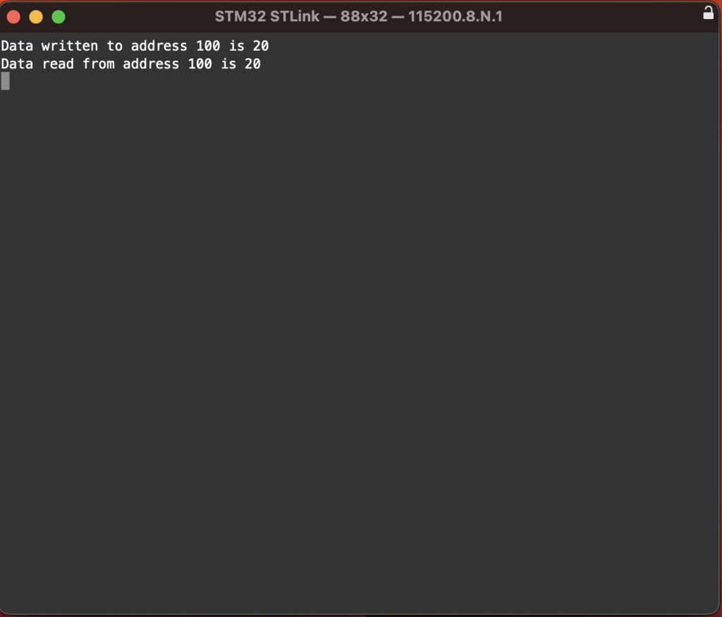
8. Results:
Open serial terminal and set the buadrate to be 115200 and you should get the following results:
Happy coding 🙂
Add Comment