
In this twelfth part of Board Support Package, we shall develop the receiver part of SPI to achieve full duplex communication with slave device which is in this case, MPU9250 sensor.
In this guide, we shall cover the following:
- Modification of header file.
- Modification of source file.
- Main code.
- Results.
1. Modification of Header File:
Starting from the previous guide here.
We shall add the following function to end of the header file spi_bsp.h
SPI_StatusTypedef BSP_SPI_Receive(SPI_TypeDef *spi ,uint8_t *data,uint32_t size, uint32_t timeout);
The function takes four argument as following:
- SPI type def to determine which SPI to be used.
- Pointer to data buffer to be read.
- Size of the buffer.
- Timeout for timeout management.
Hence, the entire header file as following:
#ifndef SPI_BSP_H_
#define SPI_BSP_H_

#include "stdint.h"
#include "stm32f4xx.h"


typedef enum
{
	spi1=0,
	spi2=1,
	spi3=2,
	spi4=3,
	spi5=4
}SPI_EnableTypedef;


typedef enum
{
	SPI_Succuss=0,
	SPI_Timeout=1,

}SPI_StatusTypedef;

typedef enum
{
	eight_bit=0,
	sixteen_bit=1,

	software_slave=1,
	hardware_slave=0,

	LSB_First=1,
	MSB_First=0,

	FCLK_2=0,
	FCLK_4=1,
	FCLK_8=2,
	FCLK_16=3,
	FCLK_32=4,
	FCLK_64=5,
	FCLK_128=6,
	FCLK_256=7,

	Master_mode=1,
	Slave_mode=0,

	CPOL0=0,
	CPOL1=1,

	CPHA0=0,
	CPHA1=1,

}SPI_ConfigurationTypedef;


typedef struct
{
	uint8_t mode;
	uint8_t dataFromat;
	uint8_t slaveManagement;
	uint8_t LSBFirst;
	uint8_t baud;
	uint8_t CPOL;
	uint8_t CPHA;
}SPI_ConfigTypedef;


void SPI_Enable_Clock(SPI_EnableTypedef spi_number);

void BSP_SPI_Config(SPI_TypeDef *spi, SPI_ConfigTypedef *con);

SPI_StatusTypedef BSP_SPI_Transmit(SPI_TypeDef *spi ,uint8_t *data,uint32_t size, uint32_t timeout);

SPI_StatusTypedef BSP_SPI_Receive(SPI_TypeDef *spi ,uint8_t *data,uint32_t size, uint32_t timeout);


#endif /* SPI_BSP_H_ */
2. Modification of Source File:
The function that reads from SPI as following:
SPI_StatusTypedef BSP_SPI_Receive(SPI_TypeDef *spi ,uint8_t *data,uint32_t size, uint32_t timeout)
{
	uint32_t start=BSP_Get_Ticks();
	while(size)
	{
		/*Send dummy data*/
		spi->DR =0;

		/*Wait for RXNE flag to be set*/
		while(!(spi->SR & (SPI_SR_RXNE)))
		{
			if((BSP_Get_Ticks()-start)>timeout){return SPI_Timeout;}
		}

		/*Read data from data register*/
		*data++ = (spi->DR);
		size--;
	}
	return SPI_Succuss;
}
We start off by declaring local variable to hold the current ticks as following:
uint32_t start=BSP_Get_Ticks();
We shall go through size in while loop as following:
while(size)
Within the while loop.
Send dummy data to keep the clock on SCK alive as following:
spi->DR =0;
Wait until the RXNE (Receiver buffer not empty):
/*Wait for RXNE flag to be set*/
while(!(spi->SR & (SPI_SR_RXNE)))
{
  if((BSP_Get_Ticks()-start)>timeout){return SPI_Timeout;}
}
Within the while loop, we shall check for timeout by simply subtracting the current ticks from the stored one and if it is bigger than timeout, the function will return timeout.
After the waiting:
- Read the DR register.
- Decrement the size variable.
/*Read data from data register*/
*data++ = (spi->DR);
size--;
Finally, return SPI_Success:
return SPI_Succuss;
Hence, the updated source file:
#include "spi_bsp.h"
#include "bsp.h"


void SPI_Enable_Clock(SPI_EnableTypedef spi_number)
{
	switch (spi_number)
	{
		case spi1: RCC->APB2ENR|=RCC_APB2ENR_SPI1EN;
			break;
		case spi2: RCC->APB1ENR|=RCC_APB1ENR_SPI2EN;
			break;
		case spi3: RCC->APB1ENR|=RCC_APB1ENR_SPI3EN;
			break;
		case spi4: RCC->APB2ENR|=RCC_APB2ENR_SPI4EN;
			break;
		case spi5: RCC->APB2ENR|=RCC_APB2ENR_SPI5EN;
			break;
		default :
			break;

	}
}

void BSP_SPI_Config(SPI_TypeDef *spi, SPI_ConfigTypedef *con)
{

	switch (con->mode)
	{

		 case Master_mode:  spi->CR1|=(1<<SPI_CR1_MSTR_Pos);
		 	 break;
		 case Slave_mode:   spi->CR1&=~(1<<SPI_CR1_MSTR_Pos); break;
		 default : break;
	}

	switch (con->dataFromat)
	{
		case MSB_First: spi->CR1&=~(con->dataFromat<<SPI_CR1_LSBFIRST_Pos);
			break;
		case LSB_First: spi->CR1|=(con->dataFromat<<SPI_CR1_LSBFIRST_Pos); break;
		default: break;
	}

	if(con->baud ==FCLK_2)
	{
		spi->CR1&=~(SPI_CR1_BR_Msk<<SPI_CR1_BR_Pos);
	}

	else
	{
		spi->CR1|=(con->baud<<SPI_CR1_BR_Pos);
	}


	if (con->CPOL==CPOL0)
	{
		spi->CR1&=~(1<<SPI_CR1_CPOL_Pos);
	}
	else
	{
		spi->CR1|=(con->CPOL<<SPI_CR1_CPOL_Pos);
	}

	if (con->CPHA==CPHA0)
	{
		spi->CR1&=~(1<<SPI_CR1_CPHA_Pos);
	}
	else
	{
		spi->CR1|=(con->CPHA<<SPI_CR1_CPHA_Pos);
	}


	switch (con->slaveManagement)
	{
	 case software_slave: spi->CR1|=(1<<SPI_CR1_SSM_Pos)|(1<<SPI_CR1_SSI_Pos); break;
	 case hardware_slave: spi->CR1&=~((1<<SPI_CR1_SSM_Pos)|(1<<SPI_CR1_SSI_Pos)); break;
	 default: break;
	}

	spi->CR1|=SPI_CR1_SPE;

}

SPI_StatusTypedef BSP_SPI_Transmit(SPI_TypeDef *spi ,uint8_t *data,uint32_t size, uint32_t timeout)
{

	uint32_t i=0;
	uint32_t start=BSP_Get_Ticks();
	while(i<size)
	{
		/*Wait until TXE is set*/
		while(!(spi->SR & (SPI_SR_TXE)))
		{
			if((BSP_Get_Ticks()-start)>timeout){return SPI_Timeout;}
		}

		/*Write the data to the data register*/
		spi->DR = data[i];
		i++;

	}
	/*Wait until TXE is set*/
	while(!(spi->SR & (SPI_SR_TXE))){if((BSP_Get_Ticks()-start)>timeout){return SPI_Timeout;}}

	/*Wait for BUSY flag to reset*/
	while((spi->SR & (SPI_SR_BSY))){if((BSP_Get_Ticks()-start)>timeout){return SPI_Timeout;}}

	/*Clear OVR flag*/
	(void)spi->DR;
	(void)spi->SR;

	return SPI_Succuss;
}


SPI_StatusTypedef BSP_SPI_Receive(SPI_TypeDef *spi ,uint8_t *data,uint32_t size, uint32_t timeout)
{
	uint32_t start=BSP_Get_Ticks();
	while(size)
	{
		/*Send dummy data*/
		spi->DR =0;

		/*Wait for RXNE flag to be set*/
		while(!(spi->SR & (SPI_SR_RXNE)))
		{
			if((BSP_Get_Ticks()-start)>timeout){return SPI_Timeout;}
		}

		/*Read data from data register*/
		*data++ = (spi->DR);
		size--;
	}
	return SPI_Succuss;
}
3. Main code:
Since this guide uses MPU9250 as slave device, you can take a look at this guide for how to connect MPU9250 in SPI.
The main.c as following:
#include "bsp.h"
#include "uart_bsp.h"
#include "exti_bsp.h"
#include "bsp_debug.h"
#include "spi_bsp.h"


void clock_config(void);


uint8_t accData[6];

GPIO_Output_Typedef CS_Pin;

#define READ_FLAG 0x80


int main()
{


	#if FPU_EN
		SCB->CPACR |= ((3UL << 10*2)|(3UL << 11*2));
	#endif

	clock_config();
	BSP_Ticks_Init(100000000);

	GPIO_Configure_Typedef PA5_SPI,PA6_SPI,PA7_SPI;

	GPIOA_CLOCK_ENABLE();

	PA5_SPI.PinNumber=5;
	PA5_SPI.Mode=Alternate_function;
	PA5_SPI.AlternateType=AF5;
	PA5_SPI.OutPutspeed=High_Speed;


	PA6_SPI.PinNumber=6;
	PA6_SPI.Mode=Alternate_function;
	PA6_SPI.AlternateType=AF5;
	PA6_SPI.OutPutspeed=High_Speed;

	PA7_SPI.PinNumber=7;
	PA7_SPI.Mode=Alternate_function;
	PA7_SPI.AlternateType=AF5;
	PA6_SPI.OutPutspeed=High_Speed;

	GPIO_Initialization(GPIOA,&PA5_SPI);
	GPIO_Initialization(GPIOA,&PA6_SPI);
	GPIO_Initialization(GPIOA,&PA7_SPI);


	GPIO_Configure_Typedef CS_Pin_Config;

	CS_Pin_Config.PinNumber=pin0;
	CS_Pin_Config.Mode=OUTPUT;
	CS_Pin_Config.OutPutspeed=High_Speed;

	GPIO_Initialization(GPIOA,&CS_Pin_Config);

	GPIO_WritePin(GPIOA,&CS_Pin,Set);

	SPI_Enable_Clock(spi1);

	SPI_ConfigTypedef cSPI1;

	cSPI1.mode=Master_mode;
	cSPI1.slaveManagement=software_slave;
	cSPI1.baud=FCLK_8;
	cSPI1.CPHA=CPHA0;
	cSPI1.CPOL=CPOL0;
	cSPI1.LSBFirst=MSB_First;


	BSP_SPI_Config(SPI1,&cSPI1);
	uint8_t addData=0x3B|READ_FLAG;
	while(1)
	{
		GPIO_WritePin(GPIOA,&CS_Pin,Reset);

		BSP_SPI_Transmit(SPI1,&addData,1,100);

		BSP_SPI_Receive(SPI1,accData,6,100);

		GPIO_WritePin(GPIOA,&CS_Pin,Set);

		BSP_Delay(10);

	}
}

void clock_config(void)
{
	Clock_Config_Typedef clockConfig;

	clockConfig.PLL_M= 4;
	clockConfig.PLL_N= 200;
	clockConfig.PLL_P= 4;

	clockConfig.AHB1Prescaler=AHB1_Prescaler1;
	clockConfig.APB1Prescaler=APB1_Prescaler2;
	clockConfig.APB2Prescaler=APB2_Prescaler1;

	clockConfig.clockSourc=External_Oscillator;
	clockConfig.flash_latency= Three_wait_state;

	Clock_Configuration(&clockConfig);
}
4. Results:
Open the debug session and set accData as variable in live expression, you should get the following results:
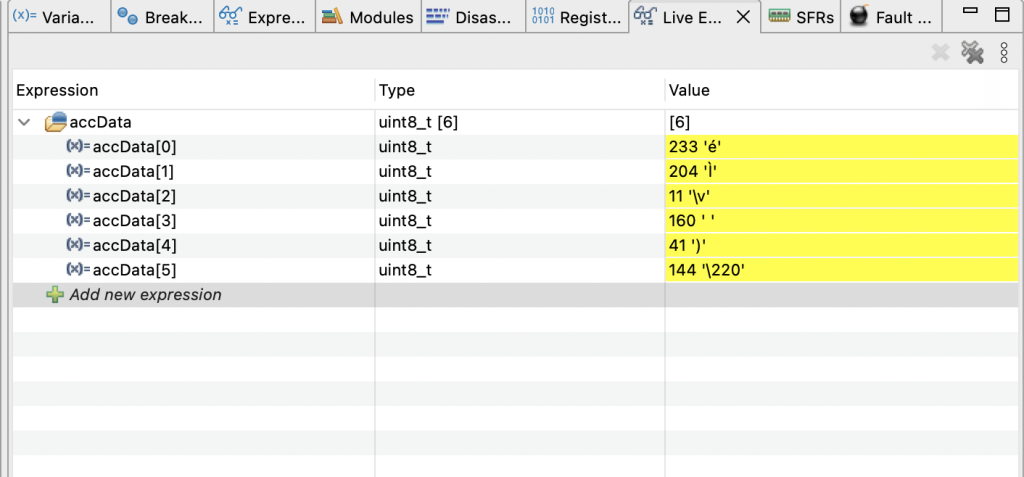
This proofs that the SPI in full duplex is working.
Happy coding 🙂
2 Comments
Dear Sir,
Namaskar, Good Morning, Pleasure to go through this site.
Please let me know in your Current list of presentations do you have…
Tutorials Regarding….(?????)….
SPI-Duplex-Mode (Rx, & Tx) CPU–Time–BlockingMode (Without Interrupts = Pollinng Method)
SPI-Duplex-Mode(Rx & Tx) CPU-Non-BlockingMode (using-Interrupts)
type A: using Secondary Memory (with out DMA) (?????)
type B: using Primary-MemoryonBoard (with DMA).
thanking you with warm regards
HSR-Rao.
Hi,
this is SPI fullduplex using DMA:
https://blog.embeddedexpert.io/?p=708
It will be revised later for improvement.
Add Comment