
In this eleventh part of Board Support Package (BSP), we shall develop SPI driver to send multiple bytes with timeout.
In this guide, we shall cover the following:
- Developing the header file.
- Developing the source file.
- Code test.
- Results.
1. Developing The Header File:
Before heading into developing the header file, you can refer to this guide about SPI and how to configure it.
Create new header file with name of spi_bsp.h.
Within the header file, include the following:
#include "stdint.h"
#include "stm32f4xx.h"
Since there are multiple SPI in STM32F411, we shall declare the following enum for clock enable functionality:
typedef enum
{
	spi1=0,
	spi2=1,
	spi3=2,
	spi4=3,
	spi5=4
}SPI_EnableTypedef;
Also, we shall declare enum to handle the status of the transmission as following:
typedef enum
{
	SPI_Succuss=0,
	SPI_Timeout=1,

}SPI_StatusTypedef;
Also, declare enum to handle the configuration as following:
typedef enum
{
	eight_bit=0,
	sixteen_bit=1,

	software_slave=1,
	hardware_slave=0,

	LSB_First=1,
	MSB_First=0,

	FCLK_2=0,
	FCLK_4=1,
	FCLK_8=2,
	FCLK_16=3,
	FCLK_32=4,
	FCLK_64=5,
	FCLK_128=6,
	FCLK_256=7,

	Master_mode=1,
	Slave_mode=0,

	CPOL0=0,
	CPOL1=1,

	CPHA0=0,
	CPHA1=1,

}SPI_ConfigurationTypedef;
The configurations as following:
- Data format: 8-bit or 16-bit.
- Software or hardware slave management.
- MSB or LSB first.
- Baudrate
- Master or slave mode.
- CPOL and CPHA mode.
Also, we shall create a structure to handle the configuration as following:
typedef struct
{
	uint8_t mode;
	uint8_t dataFromat;
	uint8_t slaveManagement;
	uint8_t LSBFirst;
	uint8_t baud;
	uint8_t CPOL;
	uint8_t CPHA;
}SPI_ConfigTypedef;
Declare the following functions:
void SPI_Enable_Clock(SPI_EnableTypedef spi_number);

void BSP_SPI_Config(SPI_TypeDef *spi, SPI_ConfigTypedef *con);

SPI_StatusTypedef BSP_SPI_Transmit(SPI_TypeDef *spi ,uint8_t *data,uint32_t size, uint32_t timeout);
Hence, the header file as following:
#ifndef SPI_BSP_H_
#define SPI_BSP_H_

#include "stdint.h"
#include "stm32f4xx.h"


typedef enum
{
	spi1=0,
	spi2=1,
	spi3=2,
	spi4=3,
	spi5=4
}SPI_EnableTypedef;


typedef enum
{
	SPI_Succuss=0,
	SPI_Timeout=1,

}SPI_StatusTypedef;

typedef enum
{
	eight_bit=0,
	sixteen_bit=1,

	software_slave=1,
	hardware_slave=0,

	LSB_First=1,
	MSB_First=0,

	FCLK_2=0,
	FCLK_4=1,
	FCLK_8=2,
	FCLK_16=3,
	FCLK_32=4,
	FCLK_64=5,
	FCLK_128=6,
	FCLK_256=7,

	Master_mode=1,
	Slave_mode=0,

	CPOL0=0,
	CPOL1=1,

	CPHA0=0,
	CPHA1=1,

}SPI_ConfigurationTypedef;


typedef struct
{
	uint8_t mode;
	uint8_t dataFromat;
	uint8_t slaveManagement;
	uint8_t LSBFirst;
	uint8_t baud;
	uint8_t CPOL;
	uint8_t CPHA;
}SPI_ConfigTypedef;


void SPI_Enable_Clock(SPI_EnableTypedef spi_number);

void BSP_SPI_Config(SPI_TypeDef *spi, SPI_ConfigTypedef *con);

SPI_StatusTypedef BSP_SPI_Transmit(SPI_TypeDef *spi ,uint8_t *data,uint32_t size, uint32_t timeout);


#endif /* SPI_BSP_H_ */
Thats all for the header file.
2. Developing The Source File:
Create new source file with name of spi_bsp.c.
Within the source file, include the following header files:
#include "spi_bsp.h"
#include "bsp.h"
For SPI clock enable function:
void SPI_Enable_Clock(SPI_EnableTypedef spi_number)
{
	switch (spi_number)
	{
		case spi1: RCC->APB2ENR|=RCC_APB2ENR_SPI1EN;
			break;
		case spi2: RCC->APB1ENR|=RCC_APB1ENR_SPI2EN;
			break;
		case spi3: RCC->APB1ENR|=RCC_APB1ENR_SPI3EN;
			break;
		case spi4: RCC->APB2ENR|=RCC_APB2ENR_SPI4EN;
			break;
		case spi5: RCC->APB2ENR|=RCC_APB2ENR_SPI5EN;
			break;
		default :
			break;

	}
}
The function takes SPI_EnableTypedef as argument to enable which SPI.
For SPI configuration function:
void BSP_SPI_Config(SPI_TypeDef *spi, SPI_ConfigTypedef *con)
{

	switch (con->mode)
	{

		 case Master_mode:  spi->CR1|=(1<<SPI_CR1_MSTR_Pos);
		 	 break;
		 case Slave_mode:   spi->CR1&=~(1<<SPI_CR1_MSTR_Pos); break;
		 default : break;
	}

	switch (con->dataFromat)
	{
		case MSB_First: spi->CR1&=~(con->dataFromat<<SPI_CR1_LSBFIRST_Pos);
			break;
		case LSB_First: spi->CR1|=(con->dataFromat<<SPI_CR1_LSBFIRST_Pos); break;
		default: break;
	}

	if(con->baud ==FCLK_2)
	{
		spi->CR1&=~(SPI_CR1_BR_Msk<<SPI_CR1_BR_Pos);
	}

	else
	{
		spi->CR1|=(con->baud<<SPI_CR1_BR_Pos);
	}


	if (con->CPOL==CPOL0)
	{
		spi->CR1&=~(1<<SPI_CR1_CPOL_Pos);
	}
	else
	{
		spi->CR1|=(con->CPOL<<SPI_CR1_CPOL_Pos);
	}

	if (con->CPHA==CPHA0)
	{
		spi->CR1&=~(1<<SPI_CR1_CPHA_Pos);
	}
	else
	{
		spi->CR1|=(con->CPHA<<SPI_CR1_CPHA_Pos);
	}


	switch (con->slaveManagement)
	{
	 case software_slave: spi->CR1|=(1<<SPI_CR1_SSM_Pos)|(1<<SPI_CR1_SSI_Pos); break;
	 case hardware_slave: spi->CR1&=~((1<<SPI_CR1_SSM_Pos)|(1<<SPI_CR1_SSI_Pos)); break;
	 default: break;
	}

	spi->CR1|=SPI_CR1_SPE;

}
For SPI transmit function:
SPI_StatusTypedef BSP_SPI_Transmit(SPI_TypeDef *spi ,uint8_t *data,uint32_t size, uint32_t timeout)
{

	uint32_t i=0;
	uint32_t start=BSP_Get_Ticks();
	while(i<size)
	{
		/*Wait until TXE is set*/
		while(!(spi->SR & (SPI_SR_TXE)))
		{
			if((BSP_Get_Ticks()-start)>timeout){return SPI_Timeout;}
		}

		/*Write the data to the data register*/
		spi->DR = data[i];
		i++;

	}
	/*Wait until TXE is set*/
	while(!(spi->SR & (SPI_SR_TXE))){if((BSP_Get_Ticks()-start)>timeout){return SPI_Timeout;}}

	/*Wait for BUSY flag to reset*/
	while((spi->SR & (SPI_SR_BSY))){if((BSP_Get_Ticks()-start)>timeout){return SPI_Timeout;}}

	/*Clear OVR flag*/
	(void)spi->DR;
	(void)spi->SR;

	return SPI_Succuss;
}
Hence, the entire source code as following:
#include "spi_bsp.h"
#include "bsp.h"


void SPI_Enable_Clock(SPI_EnableTypedef spi_number)
{
	switch (spi_number)
	{
		case spi1: RCC->APB2ENR|=RCC_APB2ENR_SPI1EN;
			break;
		case spi2: RCC->APB1ENR|=RCC_APB1ENR_SPI2EN;
			break;
		case spi3: RCC->APB1ENR|=RCC_APB1ENR_SPI3EN;
			break;
		case spi4: RCC->APB2ENR|=RCC_APB2ENR_SPI4EN;
			break;
		case spi5: RCC->APB2ENR|=RCC_APB2ENR_SPI5EN;
			break;
		default :
			break;

	}
}

void BSP_SPI_Config(SPI_TypeDef *spi, SPI_ConfigTypedef *con)
{

	switch (con->mode)
	{

		 case Master_mode:  spi->CR1|=(1<<SPI_CR1_MSTR_Pos);
		 	 break;
		 case Slave_mode:   spi->CR1&=~(1<<SPI_CR1_MSTR_Pos); break;
		 default : break;
	}

	switch (con->dataFromat)
	{
		case MSB_First: spi->CR1&=~(con->dataFromat<<SPI_CR1_LSBFIRST_Pos);
			break;
		case LSB_First: spi->CR1|=(con->dataFromat<<SPI_CR1_LSBFIRST_Pos); break;
		default: break;
	}

	if(con->baud ==FCLK_2)
	{
		spi->CR1&=~(SPI_CR1_BR_Msk<<SPI_CR1_BR_Pos);
	}

	else
	{
		spi->CR1|=(con->baud<<SPI_CR1_BR_Pos);
	}


	if (con->CPOL==CPOL0)
	{
		spi->CR1&=~(1<<SPI_CR1_CPOL_Pos);
	}
	else
	{
		spi->CR1|=(con->CPOL<<SPI_CR1_CPOL_Pos);
	}

	if (con->CPHA==CPHA0)
	{
		spi->CR1&=~(1<<SPI_CR1_CPHA_Pos);
	}
	else
	{
		spi->CR1|=(con->CPHA<<SPI_CR1_CPHA_Pos);
	}


	switch (con->slaveManagement)
	{
	 case software_slave: spi->CR1|=(1<<SPI_CR1_SSM_Pos)|(1<<SPI_CR1_SSI_Pos); break;
	 case hardware_slave: spi->CR1&=~((1<<SPI_CR1_SSM_Pos)|(1<<SPI_CR1_SSI_Pos)); break;
	 default: break;
	}

	spi->CR1|=SPI_CR1_SPE;

}

SPI_StatusTypedef BSP_SPI_Transmit(SPI_TypeDef *spi ,uint8_t *data,uint32_t size, uint32_t timeout)
{

	uint32_t i=0;
	uint32_t start=BSP_Get_Ticks();
	while(i<size)
	{
		/*Wait until TXE is set*/
		while(!(spi->SR & (SPI_SR_TXE)))
		{
			if((BSP_Get_Ticks()-start)>timeout){return SPI_Timeout;}
		}

		/*Write the data to the data register*/
		spi->DR = data[i];
		i++;

	}
	/*Wait until TXE is set*/
	while(!(spi->SR & (SPI_SR_TXE))){if((BSP_Get_Ticks()-start)>timeout){return SPI_Timeout;}}

	/*Wait for BUSY flag to reset*/
	while((spi->SR & (SPI_SR_BSY))){if((BSP_Get_Ticks()-start)>timeout){return SPI_Timeout;}}

	/*Clear OVR flag*/
	(void)spi->DR;
	(void)spi->SR;

	return SPI_Succuss;
}
3. Code Test:
In main.c:
#include "bsp.h"
#include "uart_bsp.h"
#include "exti_bsp.h"
#include "bsp_debug.h"
#include "spi_bsp.h"


void clock_config(void);


uint8_t SPI_TX_Data[5]={0x10,0x12,0x14,0x16,0x18};

GPIO_Output_Typedef CS_Pin;


int main()
{


	#if FPU_EN
		SCB->CPACR |= ((3UL << 10*2)|(3UL << 11*2));
	#endif

	clock_config();
	BSP_Ticks_Init(100000000);

	GPIO_Configure_Typedef PA5_SPI,PA6_SPI,PA7_SPI;

	GPIOA_CLOCK_ENABLE();

	PA5_SPI.PinNumber=5;
	PA5_SPI.Mode=Alternate_function;
	PA5_SPI.AlternateType=AF5;
	PA5_SPI.OutPutspeed=High_Speed;


	PA6_SPI.PinNumber=6;
	PA6_SPI.Mode=Alternate_function;
	PA6_SPI.AlternateType=AF5;
	PA6_SPI.OutPutspeed=High_Speed;

	PA7_SPI.PinNumber=7;
	PA7_SPI.Mode=Alternate_function;
	PA7_SPI.AlternateType=AF5;
	PA6_SPI.OutPutspeed=High_Speed;

	GPIO_Initialization(GPIOA,&PA5_SPI);
	GPIO_Initialization(GPIOA,&PA6_SPI);
	GPIO_Initialization(GPIOA,&PA7_SPI);


	GPIO_Configure_Typedef CS_Pin_Config;

	CS_Pin_Config.PinNumber=pin0;
	CS_Pin_Config.Mode=OUTPUT;
	CS_Pin_Config.OutPutspeed=High_Speed;

	GPIO_Initialization(GPIOA,&CS_Pin_Config);

	GPIO_WritePin(GPIOA,&CS_Pin,Set);

	SPI_Enable_Clock(spi1);

	SPI_ConfigTypedef cSPI1;

	cSPI1.mode=Master_mode;
	cSPI1.slaveManagement=software_slave;
	cSPI1.baud=FCLK_64;
	cSPI1.CPHA=CPHA0;
	cSPI1.CPOL=CPOL0;
	cSPI1.LSBFirst=MSB_First;


	BSP_SPI_Config(SPI1,&cSPI1);

	while(1)
	{
		GPIO_WritePin(GPIOA,&CS_Pin,Reset);

		BSP_SPI_Transmit(SPI1,SPI_TX_Data,5,100);

		GPIO_WritePin(GPIOA,&CS_Pin,Set);

		BSP_Delay(10);

	}
}

void clock_config(void)
{
	Clock_Config_Typedef clockConfig;

	clockConfig.PLL_M= 4;
	clockConfig.PLL_N= 200;
	clockConfig.PLL_P= 4;

	clockConfig.AHB1Prescaler=AHB1_Prescaler1;
	clockConfig.APB1Prescaler=APB1_Prescaler2;
	clockConfig.APB2Prescaler=APB2_Prescaler1;

	clockConfig.clockSourc=External_Oscillator;
	clockConfig.flash_latency= Three_wait_state;

	Clock_Configuration(&clockConfig);
}
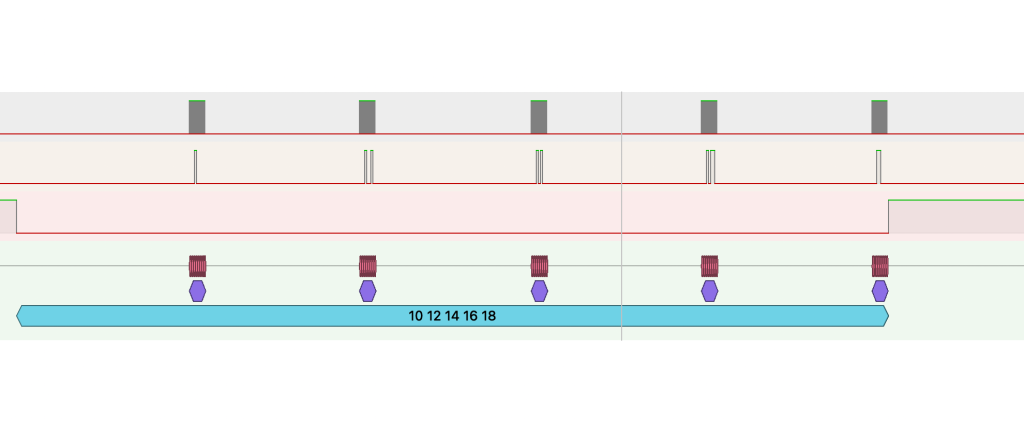
4. Results:
By using logic analyzer, connect pins PA0(CS), PA5 (SCK) and PA7 (MOSI) to logic analyzer and you should get the following results:
Happy coding 🙂
Add Comment