
In the previous guide (here), we took a look at board support package and how to configure a pin to act as input and output. In this guide, we shall build board support package to set the frequency of the core.
In this guide, we shall cover the following:
- Building the header file.
- Building the source file.
- Core configuration.
- Code.
- Results.
1. Building the header file:
From the previous guide, open bsp.h header file.
We start off by declaring enum to hold AHB1 Prescaler values:
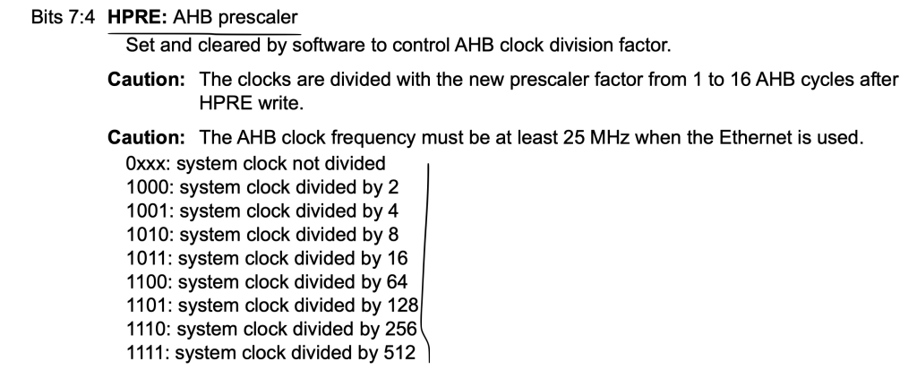
typedef enum
{
	AHB1_Prescaler1=0,
	AHB1_Prescaler2=0x8,
	AHB1_Prescaler4=0x09,
	AHB1_Prescaler8=0x0A,
	AHB1_Prescaler16=0x0B,
	AHB1_Prescaler64=0x0C,
	AHB1_Prescaler128=0x0D,
	AHB1_Prescaler256=0x0E,
	AHB1_Prescaler512=0x0F

}AHB1_Prescalers_Typedef;
Enum to hold the APB1 prescalers:
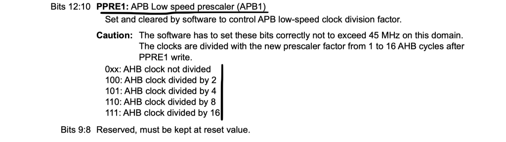
typedef enum
{
	APB1_Prescaler1=0x00,
	APB1_Prescaler2=0x04,
	APB1_Prescaler4=0x05,
	APB1_Prescaler8=0x06,
	APB1_Prescaler16=0x07
}APB1_Prescalers_Typedef;
Similar to APB2:
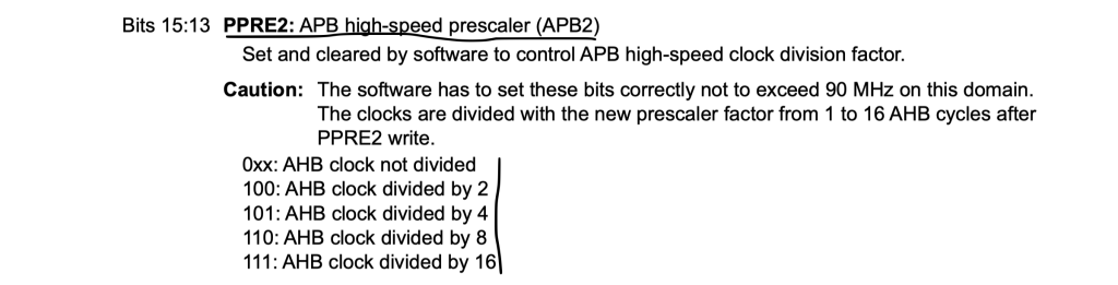
typedef enum
{
	APB2_Prescaler1=0x00,
	APB2_Prescaler2=0x04,
	APB2_Prescaler4=0x05,
	APB2_Prescaler8=0x06,
	APB2_Prescaler16=0x07
}APB2_Prescalers_Typedef;
We also create enum to hold if we want to use the internal or external oscillator when we configure the core:
typedef enum
{
	Internal_Oscillator=0,
	External_Oscillator=1
}Clock_Source_Typedef;
When the core frequency is changed, you need to configure the flash latency. We shall create enum to hold all flash latency configurations as following:
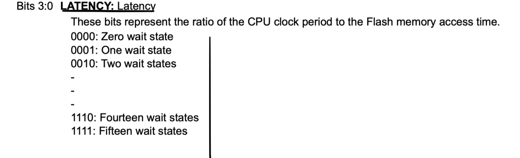
typedef enum

{
	Zero_wait_state=0,
	One_wait_state,
	Two_wait_state,
	Three_wait_state,
	Four_wait_state,
	five_wait_state,
	six_wait_state,
	seven_wait_state,
	eight_wait_state,
	nine_wait_state,
	Ten_wait_state,
	Eleven_wait_state,
	Twelve_wait_state,
	Thirteen_wait_state,
	Fourteen_wait_state,
	Fifteen_wait_state
}Flash_Latency_Typedef;
Enum to hold if the setting the core was success or not:
typedef enum
{
	success=0,
	failed=1

}Clock_Config_State_Typedef;
Create a new data structure to include the following variables:
- Clock source.
- PLL_M, PLL_N, PLL_P values.
- flash latency value.
- AHB1, APB1 and APB2 prescaler value.
typedef struct
{
	uint8_t clockSourc;

	uint16_t PLL_M;
	uint16_t PLL_N;
	uint16_t PLL_P;

	uint8_t flash_latency;

	uint8_t AHB1Prescaler;
	uint8_t APB1Prescaler;
	uint8_t APB2Prescaler;


}Clock_Config_Typedef;
Create a function that returns Clock_Config_State_Typedef and takes pointer Clock_Config_Typedef data structure as an argument:
Clock_Config_State_Typedef Clock_Confgiuration(Clock_Config_Typedef * config);
2. Developing the source file:
For more details how to get, PLL_M, PLL_N and PLL_P, please refer to this guide here.
Open bsp.c source file and include the following function:
Clock_Config_State_Typedef Clock_Confgiuration(Clock_Config_Typedef * config)
within the function, check if the clock source is the external or not:
if (config->clockSourc==External_Oscillator)
If it is, enable the external oscillator:
Before enable the oscillator, declare some variable to help determine if the external oscillator is enabled or timed out.
__IO uint32_t StartUpCounter = 0, HSEStatus = 0;
Enable the external oscillator:
RCC->CR |= RCC_CR_HSEON;
Wait until the external oscillator is enabled or timed out:
		do
		{
			HSEStatus = RCC->CR & RCC_CR_HSERDY;
			StartUpCounter++;
		} while((HSEStatus == 0) && (StartUpCounter != 3000));
Check if the oscillator is enabled, if it is, proceed to core configuration as following:
			RCC->APB1ENR |= RCC_APB1ENR_PWREN; //enable power regulator
			PWR->CR &= (uint32_t)~(PWR_CR_VOS); //reset VOS (mode 3 selected)

			RCC->CFGR |=(config->AHB1Prescaler<<RCC_CFGR_HPRE_Pos); /*Configure AHB bus prescaler*/

			RCC->CFGR |= (config->APB2Prescaler<<RCC_CFGR_PPRE2_Pos); /*Configure APB2 bus prescaler*/

			RCC->CFGR |= (config->APB1Prescaler<<RCC_CFGR_PPRE1_Pos); /*Configure APB1 bus prescaler*/

		    RCC->PLLCFGR = config->PLL_M | (config->PLL_N << 6) | (((config->PLL_P >> 1) -1) << 16) | //set PLL_M,PLL_N,PLL_P
		                   (RCC_PLLCFGR_PLLSRC_HSE) /*Set PLL clock source to be external oscillator*/;

		    RCC->CR |= RCC_CR_PLLON; //turn on the PLL


		    while((RCC->CR & RCC_CR_PLLRDY) == 0) //wait untill PLL is active
		    {
		    }

		    /* Configure Flash prefetch, Instruction cache, Data cache and wait state */
		       FLASH->ACR = FLASH_ACR_ICEN |FLASH_ACR_DCEN |(config->flash_latency<<FLASH_ACR_LATENCY_Pos);

		       /* Select the main PLL as system clock source */
		       RCC->CFGR &= (uint32_t)((uint32_t)~(RCC_CFGR_SW));
		       RCC->CFGR |= RCC_CFGR_SW_PLL;

		       /* Wait till the main PLL is used as system clock source */
		       while ((RCC->CFGR & (uint32_t)RCC_CFGR_SWS ) != RCC_CFGR_SWS_PLL)
		       {;}
If the external oscillator failed to start, return failed:
else
		{
			return failed;
		}
If the internal one is selected, configure the clock and return success as following:
else
	{
		RCC->APB1ENR |= RCC_APB1ENR_PWREN; //enable power regulator
		PWR->CR &= (uint32_t)~(PWR_CR_VOS); //reset VOS (mode 3 selected)

		RCC->CFGR |=(config->AHB1Prescaler<<RCC_CFGR_HPRE_Pos); /*Configure AHB bus prescaler*/

		RCC->CFGR |= (config->APB2Prescaler<<RCC_CFGR_PPRE2_Pos);

		RCC->CFGR |= (config->APB1Prescaler<<RCC_CFGR_PPRE1_Pos);

		RCC->PLLCFGR = config->PLL_M | (config->PLL_N << 6) | (((config->PLL_P >> 1) -1) << 16); //set PLL_M,PLL_N,PLL_P


		RCC->CR |= RCC_CR_PLLON; //turn on the PLL


		while((RCC->CR & RCC_CR_PLLRDY) == 0) //wait untill PLL is active
		{
		}

		/* Configure Flash prefetch, Instruction cache, Data cache and wait state */
		FLASH->ACR = FLASH_ACR_ICEN |FLASH_ACR_DCEN |(config->flash_latency<<FLASH_ACR_LATENCY_Pos);

		/* Select the main PLL as system clock source */
		RCC->CFGR &= (uint32_t)((uint32_t)~(RCC_CFGR_SW));
		RCC->CFGR |= RCC_CFGR_SW_PLL;

		/* Wait till the main PLL is used as system clock source */
		while ((RCC->CFGR & (uint32_t)RCC_CFGR_SWS ) != RCC_CFGR_SWS_PLL)
		{;}
	}


	return success;
Hence, the core configuration function as following:
Clock_Config_State_Typedef  Clock_Confgiuration(Clock_Config_Typedef * config)
{
	if (config->clockSourc==External_Oscillator)
	{
		__IO uint32_t StartUpCounter = 0, HSEStatus = 0;


		RCC->CR |= ((uint32_t)RCC_CR_HSEON);


		do
		{
			HSEStatus = RCC->CR & RCC_CR_HSERDY;
			StartUpCounter++;
		} while((HSEStatus == 0) && (StartUpCounter != 3000));

		if ((RCC->CR & RCC_CR_HSERDY) != RESET) //HSE enabled
		{
			RCC->APB1ENR |= RCC_APB1ENR_PWREN; //enable power regulator
			PWR->CR &= (uint32_t)~(PWR_CR_VOS); //reset VOS (mode 3 selected)

			RCC->CFGR |=(config->AHB1Prescaler<<RCC_CFGR_HPRE_Pos); /*Configure AHB bus prescaler*/

			RCC->CFGR |= (config->APB2Prescaler<<RCC_CFGR_PPRE2_Pos); /*Configure APB2 bus prescaler*/

			RCC->CFGR |= (config->APB1Prescaler<<RCC_CFGR_PPRE1_Pos); /*Configure APB1 bus prescaler*/

		    RCC->PLLCFGR = config->PLL_M | (config->PLL_N << 6) | (((config->PLL_P >> 1) -1) << 16) | //set PLL_M,PLL_N,PLL_P
		                   (RCC_PLLCFGR_PLLSRC_HSE) /*Set PLL clock source to be external oscillator*/;

		    RCC->CR |= RCC_CR_PLLON; //turn on the PLL


		    while((RCC->CR & RCC_CR_PLLRDY) == 0) //wait untill PLL is active
		    {
		    }

		    /* Configure Flash prefetch, Instruction cache, Data cache and wait state */
		       FLASH->ACR = FLASH_ACR_ICEN |FLASH_ACR_DCEN |(config->flash_latency<<FLASH_ACR_LATENCY_Pos);

		       /* Select the main PLL as system clock source */
		       RCC->CFGR &= (uint32_t)((uint32_t)~(RCC_CFGR_SW));
		       RCC->CFGR |= RCC_CFGR_SW_PLL;

		       /* Wait till the main PLL is used as system clock source */
		       while ((RCC->CFGR & (uint32_t)RCC_CFGR_SWS ) != RCC_CFGR_SWS_PLL)
		       {;}

		}
		else
		{
			return failed;
		}


	}

	else
	{
		RCC->APB1ENR |= RCC_APB1ENR_PWREN; //enable power regulator
		PWR->CR &= (uint32_t)~(PWR_CR_VOS); //reset VOS (mode 3 selected)

		RCC->CFGR |=(config->AHB1Prescaler<<RCC_CFGR_HPRE_Pos); /*Configure AHB bus prescaler*/

		RCC->CFGR |= (config->APB2Prescaler<<RCC_CFGR_PPRE2_Pos);

		RCC->CFGR |= (config->APB1Prescaler<<RCC_CFGR_PPRE1_Pos);

		RCC->PLLCFGR = config->PLL_M | (config->PLL_N << 6) | (((config->PLL_P >> 1) -1) << 16); //set PLL_M,PLL_N,PLL_P


		RCC->CR |= RCC_CR_PLLON; //turn on the PLL


		while((RCC->CR & RCC_CR_PLLRDY) == 0) //wait untill PLL is active
		{
		}

		/* Configure Flash prefetch, Instruction cache, Data cache and wait state */
		FLASH->ACR = FLASH_ACR_ICEN |FLASH_ACR_DCEN |(config->flash_latency<<FLASH_ACR_LATENCY_Pos);

		/* Select the main PLL as system clock source */
		RCC->CFGR &= (uint32_t)((uint32_t)~(RCC_CFGR_SW));
		RCC->CFGR |= RCC_CFGR_SW_PLL;

		/* Wait till the main PLL is used as system clock source */
		while ((RCC->CFGR & (uint32_t)RCC_CFGR_SWS ) != RCC_CFGR_SWS_PLL)
		{;}
	}


	return success;
}
Thats all for the source file.
3. Core Configuration:
in main.c:
#include "bsp.h"

GPIO_Output_Typedef LED;


Clock_Config_Typedef clockConfig;

void delay(int ms)
{
	SysTick->LOAD=100000-1;
	SysTick->VAL=0;
	SysTick->CTRL=0x5;
		for (int i=0;i<ms;i++)
		{
			while(!(SysTick->CTRL &0x10000)){}
		}
	SysTick->CTRL=0;
}


int main()
{


	GPIOA_CLOCK_ENABLE();

	GPIO_Configure_Typedef LED_Config;

	LED_Config.PinNumber=pin5;
	LED_Config.Mode=OUTPUT;

	LED.pinNumber=pin5;

	GPIO_Initialization(GPIOA,&LED_Config);

	clockConfig.PLL_M= 4;
	clockConfig.PLL_N= 200;
	clockConfig.PLL_P= 4;

	clockConfig.AHB1Prescaler=AHB1_Prescaler1;
	clockConfig.APB1Prescaler=APB1_Prescaler2;
	clockConfig.APB2Prescaler=APB2_Prescaler1;

	clockConfig.clockSourc=External_Oscillator;
	clockConfig.flash_latency= Three_wait_state;

	Clock_Confgiuration(&clockConfig);

	while(1)
	{

		GPIO_TogglePin(GPIOA, &LED);
		delay(1000);

	}

}
We used systick to confirm that we got 100MHz.
4. Code:
You may download the source code from here:
5. Results:
Happy coding 🙂
2 Comments
Dear Sir,
Requesting you to kindly review these lines in this tutorial.
correct me if I my understanding is wrong.
thanks with regards,
HSR-Rao.
typedef enum {
1011: system clock divided by 16 AHB1_Prescaler16= 0x0B,
1100: system clock divided by 64 AHB1_Prescaler32= 0x0C, <==to be changed
1101: system clock divided by 128 AHB1_Prescaler164= 0x0D, <==to be changed
1110: system clock divided by 256 AHB1_Prescaler128= 0x0E, <==to be changed
1111: system clock divided by 512 AHB1_Prescaler256= 0x0F <==to be changed
}AHB1_Prescalers_Typedef;
Hi,
yes, you are correct.
Will change them.
I was looking at another MCU reference manual which had these value. My mistake.
Add Comment