
In this guide, we shall see what is Board Support package and how to build one for STM32F411-Nucleo64. In this guide, we shall see how to configure the GPIO input mode and output.
In this guide, we shall cover the following:
- What is BSP.
- Building the header file.
- Building the source file.
- Code.
- Results.
1. What is Board Support Package:
In embedded systems, a board support package (BSP) is the layer of software containing hardware-specific boot firmware and device drivers and other routines that allow a given embedded operating system, for example a real-time operating system (RTOS), to function in a given hardware environment (a motherboard), integrated with the embedded operating system. Aslo, A Board Support Package (BSP) is a collection of drivers customized to the provided hardware description. Every application must be associated with a BSP. Multiple BSPs may exist in a workspace and support a single hardware description. Often BSPs are created when an Application is created.
2. Building the header file:
We start off by creating a header file with name of bsp.h.
Within the header file, include the header guard as following:
#ifndef BSP_H_
#define BSP_H_


#endif /* BSP_H_ */
Within the header guard, include the following header files:
- stdint.
- stm32f4xx.h file
#include "stdint.h"
#include "stm32f4xx.h"
Since out MCU has pins from 0 to 15, we shall create an enum to hold the pin numbers as following:
typedef enum
{
	pin0=0,
	pin1,
	pin2,
	pin3,
	pin4,
	pin5,
	pin6,
	pin7,
	pin8,
	pin9,
	pin10,
	pin11,
	pin12,
	pin13,
	pin14,
	pin15
}Pins_Typedef;
This will allow us to declare the pin number in more readable format.
Since each GPIO has four modes as following:
- General Purpose Input.
- General Purpose Output.
- Alterante Mode.
- Analog Mode.
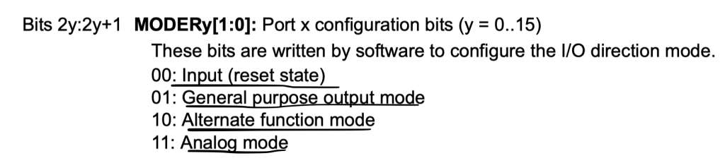
We shall create enum to hold those types as following:
typedef enum
{
	INPUT=0,
	OUTPUT,
	Alternate_function,
	Analog_Mode

}GPIO_ModeTypedef;
When the GPIO pin is declared as output, it has two output type:
- Push Pull.
- Open Drain.
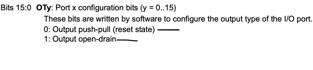
Hence, we can create an enum to hold these type as following:
typedef enum
{
	Push_Pull=0,
	Open_Drain
}GPIO_Output_Type_Typedef;
Also, for output, we have four speed setting as following:
- Low speed.
- Medium speed.
- Fast speed.
- High speed.
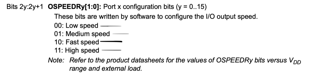
We shall create enum to hold those variable as following:
typedef enum
{
	Low_Speed=0,
	Medium_Speed,
	Fast_Speed,
	High_Speed
}GPIO_OutputSpeed_Typedef;
When a GPIO pin is declares as input, we can activate one of the following three states:
- No Pullup or pulldown.
- Pullup.
- Pulldown.
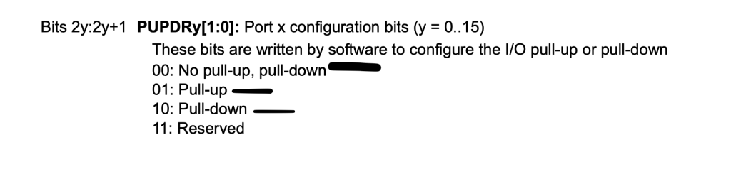
We shall create enum to hold those variable:
typedef enum
{
	No_Pullup_PullDown=0,
	PullUp,
	PullDown
}GPIO_PullUPPullDown_Typedef;
We shall create enum to hold the alternate functions number as following:
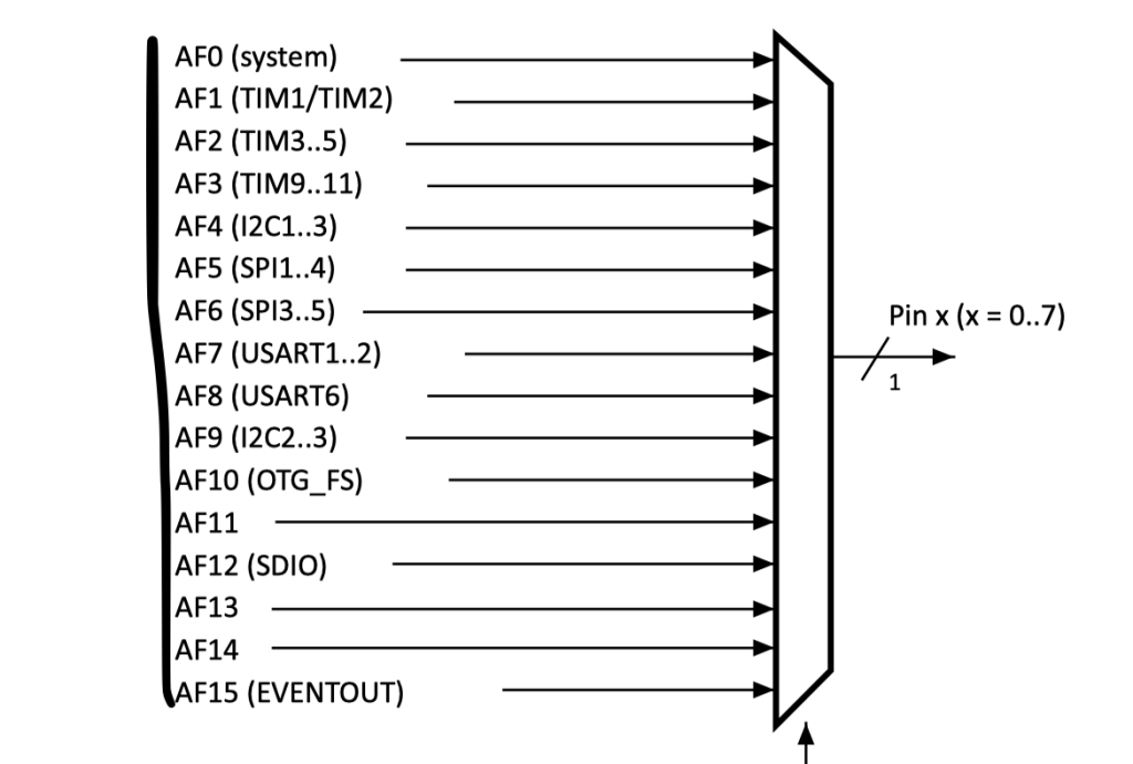
typedef enum
{
	AF0=0,
	AF1,
	AF2,
	AF3,
	AF4,
	AF5,
	AF6,
	AF7,
	AF8,
	AF9,
	AF10,
	AF11,
	AF12,
	AF13,
	AF14,
	AF15,

}Alternate_Type_Typedef;
We shall also create enum to hold the state of the pin:
- Reset which means 0.
- Set which means 1.
typedef enum
{
	Reset,
	Set

}GPIO_State_Typedef;
Now, we shall declare a structure to hold the following parameters of GPIO:
- Pin Number.
- Mode.
- Output Type.
- Output Speed.
- Pullup Pulldown.
- Alternate type.
The alternate function shall be handled later.
typedef struct
{
	uint8_t PinNumber;
	uint8_t Mode;
	uint8_t OutputType;
	uint8_t OutPutspeed;
	uint8_t PullUp_PullDown;
	uint8_t AlternateType;

}GPIO_Configure_Typedef;
Also, a data structure to hold the output pin number and state.
typedef struct
{
	uint8_t pinNumber;
	uint8_t state;
}GPIO_Output_Typedef;
A data structure to hold the pin number only when it is input mode.
typedef struct
{
	uint8_t pinNumber;
}GPIO_Input_Typedef;
Aslo, declare the following 6 functions:
void GPIOA_CLOCK_ENABLE();

void GPIOC_CLOCK_ENABLE();

void GPIO_Initialization(GPIO_TypeDef *GPIO,GPIO_Configure_Typedef *GPIO_Config);

void GPIO_WritePin(GPIO_TypeDef *GPIO,GPIO_Output_Typedef *GPIOPin, GPIO_State_Typedef state );

void GPIO_TogglePin(GPIO_TypeDef *GPIO,GPIO_Output_Typedef *GPIOPin);

GPIO_State_Typedef GPIO_ReadPin(GPIO_TypeDef *GPIO,GPIO_Input_Typedef *pin);
3. Building the source file:
Create new source file with name of bsp.c.
Within the source file, include the header file of bsp.h:
#include "bsp.h"
First function is to enable GPIOA clock access as following:
void GPIOA_CLOCK_ENABLE()
{
	RCC->AHB1ENR|= RCC_AHB1ENR_GPIOAEN;
}
For GPIOC:
void GPIOC_CLOCK_ENABLE()
{
	RCC->AHB1ENR|= RCC_AHB1ENR_GPIOCEN;
}
For more information about enabling clock access to certain port, please refer to this guide.
For GPIO initializing function:
void GPIO_Initialization(GPIO_TypeDef *GPIO,GPIO_Configure_Typedef * GPIO_Config)
{
	if (GPIO_Config->Mode !=Alternate_function)
	{


		GPIO->MODER &=~((0x03<<(GPIO_Config->PinNumber*2)));
		GPIO->MODER|= (GPIO_Config->Mode<< GPIO_Config->PinNumber*2);

		GPIO->OTYPER|= (GPIO_Config->OutputType<<GPIO_Config->PinNumber);

		GPIO->OSPEEDR|= (GPIO_Config->OutPutspeed<< GPIO_Config->PinNumber*2);

		GPIO->PUPDR|= (GPIO_Config->PullUp_PullDown<< GPIO_Config->PinNumber*2);
	}

}
The function takes two arguments:
- Pointer to GPIO_TypeDef which holds which GPIO port to access (e.g. GPIOA).
- Pointer to GPIO_Cofiguration_TypeDet which holds the GPIO configuration.
Within the function:
Check if the mode is not alternate function since the alternate function shall be handled alter.
If mode is not alternate function, set the pin according the use configuration.
For the GPIO_WritePin function:
void GPIO_WritePin(GPIO_TypeDef *GPIO,GPIO_Output_Typedef *GPIOPin, GPIO_State_Typedef state )
{

	switch (state)
	{
		case Reset:
			GPIO->BSRR = (1<<((GPIOPin->pinNumber) +16));
			GPIOPin->state=Reset;
			break;

		case Set:
			GPIO->BSRR = (1<<(GPIOPin->pinNumber));
			GPIOPin->state=Set;
			break;

		default: break;
	}
}
The function takes three parameters:
- Pointer to GPIO_Typedef which hold GPIO to be access.
- Pointer to GPIO_OutPut_Typedef which holds which pin to be controlled.
- Third parameter is the enum which holds the state.
Within the function, check which state is desired and set/reset the pin and also set the pin state variable to the desired state.
For GPIO_TogglePin:
void GPIO_TogglePin(GPIO_TypeDef *GPIO,GPIO_Output_Typedef *GPIOPin)
{
	switch (GPIOPin->state)
	{
		case Reset:
			GPIO->BSRR = (1<<(GPIOPin->pinNumber));
			GPIOPin->state=Set;
			break;

		case Set:
			GPIO->BSRR = (1<<((GPIOPin->pinNumber) +16));
			GPIOPin->state=Reset;
			break;
	}
}
The function takes two parameter:
Within the function, check the state and set the pin to the other state. i.e. set to reset and vice versa.
For GPIO_ReadPin function:
GPIO_State_Typedef GPIO_ReadPin(GPIO_TypeDef *GPIO,GPIO_Input_Typedef *pin)
{
	uint8_t temp;
	temp= (GPIO->IDR & (1<<pin->pinNumber))>>pin->pinNumber;
	return temp;
}
The function takes two parameters:
The function will return GPIO_State_Typedef which either set or reset.
In main.c :
Include the board support package:
#include "bsp.h"
Declare the structure of LED as output and Button as input:
GPIO_Output_Typedef LED;

GPIO_Input_Typedef Button;
in int main function:
int main()
Enable clock access to GPIO and GPIOC as following:
GPIOA_CLOCK_ENABLE();
GPIOC_CLOCK_ENABLE();
Declare the LED configuration structure and set the parameters and initialize the LED:
	GPIO_Configure_Typedef LED_Config;

	LED_Config.PinNumber=pin5;
	LED_Config.Mode=OUTPUT;

	LED.pinMumber=pin5;

	GPIO_Initialization(GPIOA,&LED_Config);
For the button configuration:
	GPIO_Configure_Typedef Button_Config;

	Button.pinMumber=pin13;
	Button_Config.PinNumber=pin13;
	Button_Config.Mode=INPUT;

	GPIO_Initialization(GPIOC,&Button_Config);
In while(1):
while(1)
	{
		uint8_t state=GPIO_ReadPin(GPIOC,&Button);
		GPIO_WritePin(GPIOA, &LED,state);

	}
Hence, the main.c:
#include "bsp.h"

GPIO_Output_Typedef LED;

GPIO_Input_Typedef Button;

int main()
{
	GPIOA_CLOCK_ENABLE();
	GPIOC_CLOCK_ENABLE();

	GPIO_Configure_Typedef LED_Config;

	LED_Config.PinNumber=pin5;
	LED_Config.Mode=OUTPUT;

	LED.pinNumber=pin5;

	GPIO_Initialization(GPIOA,&LED_Config);

	GPIO_Configure_Typedef Button_Config;

	Button.pinMumber=pin13;
	Button_Config.PinNumber=pin13;
	Button_Config.Mode=INPUT;

	GPIO_Initialization(GPIOC,&Button_Config);

	while(1)
	{
		uint8_t state=GPIO_ReadPin(GPIOC,&Button);
		GPIO_WritePin(GPIOA, &LED,state);

	}

}
4. Code:
You may download the source code from here:
5. Results:
Happy coding 🙂
Add Comment