In this two part series guide, we shall interface HM10 BLE module with STM32 and control an LED and send string from STM32.
In this guide, we shall cover the following:
- What is HM-10.
- Connection.
- UART setup.
- LED Setup.
- Time base setup.
- code.
1. What is HM-10:
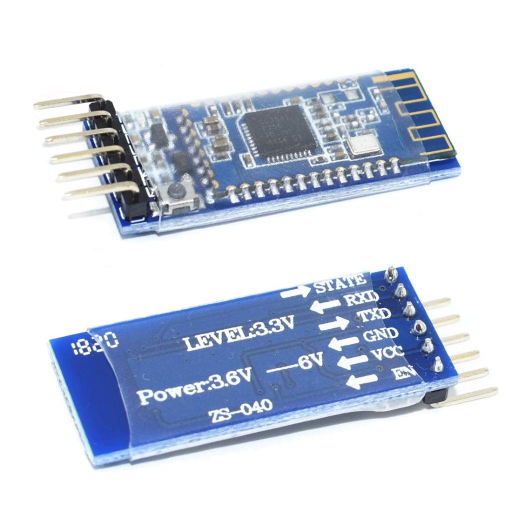
The HM-10 is a readily available Bluetooth 4.0 module used for establishing wireless data communication. The module is designed by using the Texas Instruments CC2540 or CC2541 Bluetooth low energy (BLE) System on Chip (SoC) but design and firmware originated from the Jinan Huamao Technology Company.
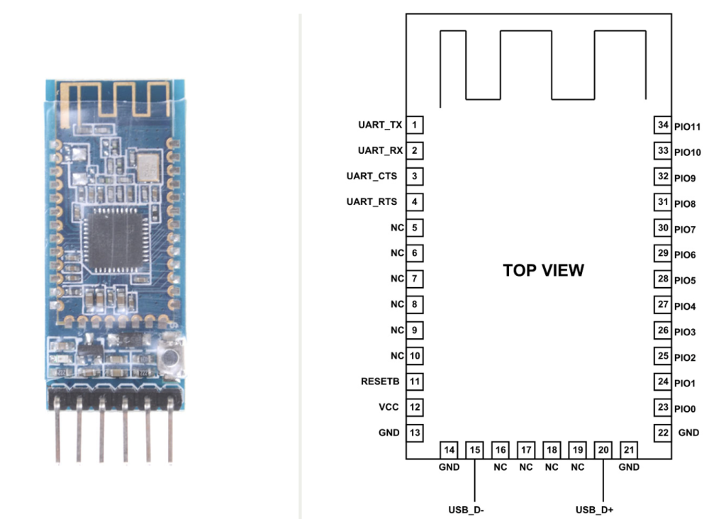
HM-10 Pinout Configuration
HM-10 is a 34-pin module. In them most are not compulsory use pins. We only need four pins of all 34 to establish a communication. We will describe the function of each pin below.
| Pin Number | Pin Name | Description |
| 1 | UART_TX | UART interface-Transmit |
| 2 | UART_RX | UART interface-Receive |
| 3 | UART_CTS | UART interface |
| 4 | UART_RTS | UART interface |
| 5 | NC | No Connection |
| 6 | NC | No Connection |
| 7 | NC | No Connection |
| 8 | NC | No Connection |
| 9 | NC | No Connection |
| 10 | NC | No Connection |
| 11 | RESETB | Reset if low for 100ms |
| 12 | VCC | 3.3V |
| 13 | GND | Ground |
| 14 | GND | Ground |
| 15 | USB_D- | USB interface |
| 16 | NC | No Connection |
| 17 | NC | No Connection |
| 18 | NC | No Connection |
| 19 | NC | No Connection |
| 20 | USB_D+ | USB interface |
| 21 | GND | Ground |
| 22 | GND | Ground |
| 23 | PIO0 | System Key |
| 24 | PIO1 | System LED |
| 25 | PIO2 | Programmable input/output line |
| 26 | PIO3 | Programmable input/output line |
| 27 | PIO4 | Programmable input/output line |
| 28 | PIO5 | Programmable input/output line |
| 29 | PIO6 | Programmable input/output line |
| 30 | PIO7 | Programmable input/output line |
| 31 | PIO8 | Programmable input/output line |
| 32 | PIO9 | Programmable input/output line |
| 33 | PIO10 | Programmable input/output line |
| 34 | PIO11 | Programmable input/output line |
HM-10 Module Features
- BT Version: Bluetooth Specification V4.0
- BLE chip – Bluetooth Low Energy consumption
- Send and receive no bytes limit.
- Working frequency: 2.4GHz ISM band
- UART Serial Interface
- Full-Speed USB Interface
- 12 General Purpose Input/output Pins
- In-System-Programmable Flash- 128 KB or 256KB
- 8-KB SRAM
- 32-kHz Sleep Timer With Capture
- Long range: Open space have 100 Meters
- Potable size
- HM-10 MODULE Specifications
- Operating voltage of MODULE: 2.0V – 3.6V
- Can operate on LOW voltages
- Consumes 235uA on battery backup
- Input RF level: 10dBm
- Maximum voltage: + 3.9V
- Operating temperature: -40ºC to +85ºC
- ESD: 750V
For more information, please refer to the datasheet from here.
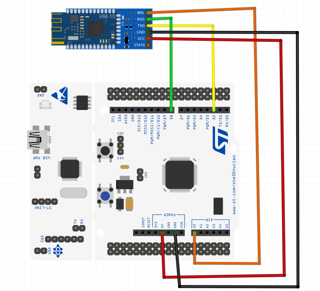
2. Connection:
In this guide, we need sing STM32F4 and single HC-12 module in order to make communication between iPhone and STM32:
The connection as following:
| STM32F44 | HM-10 Module |
| 5V | Vcc |
| GND | GND |
| PA9 (UART1_TX) | RX |
| PA10(UART1_RX) | TX |
| PA0 | Key |
3. UART setup:
We start off by creating new source and header file with name of hm10_uart.c and hm10_uart.h respectively.
Te utilitized UART is UART1 which will receive data using interrupt:
To see how to setup UART from scratch and everything related to it, please refer to this topic.
Within the header file:
#ifndef HM_10_UART_H_
#define HM_10_UART_H_

#include "stdint.h"

void hm10_uart_init(uint32_t baud,uint32_t freq);

void hm10_write_char(unsigned char ch);

void hm10_write_at_command(unsigned char * ch);

void hm10_write_string(unsigned char * ch);


#endif /* HM_10_UART_H_ */
Within source file:
#include <hm_10_uart.h>
#include "stm32f4xx.h"


#define AF07 0x07


static void uart_set_baudrate(USART_TypeDef *USARTx, uint32_t PeriphClk,  uint32_t BaudRate);


void hm10_uart_init(uint32_t baud,uint32_t freq)
{
	/*Enable clock access to GPIOA and USART1*/
	RCC->APB2ENR|=RCC_APB2ENR_USART1EN;
	RCC->AHB1ENR|=RCC_AHB1ENR_GPIOAEN;
	/*Configure the GPIO for UART Mode*/
	GPIOA->MODER|=GPIO_MODER_MODE9_1;
	GPIOA->MODER&=~GPIO_MODER_MODE9_0;
	GPIOA->MODER|=GPIO_MODER_MODE10_1;
	GPIOA->MODER&=~GPIO_MODER_MODE10_0;
	GPIOA->AFR[1]|=(AF07<<GPIO_AFRH_AFSEL9_Pos)|(AF07<<GPIO_AFRH_AFSEL10_Pos); //ALT7 for UART1 (PA9 and PA10)
	/*Configure UART*/
	uart_set_baudrate(USART1,freq,baud);
	USART1->CR1|=USART_CR1_TE|USART_CR1_RE;
	USART1->CR1|=USART_CR1_RXNEIE;
	NVIC_EnableIRQ(USART1_IRQn);
	USART1->CR1|=USART_CR1_UE;
}

static uint16_t compute_uart_bd(uint32_t PeriphClk, uint32_t BaudRate)
{
	return ((PeriphClk + (BaudRate/2U))/BaudRate);
}

static void uart_set_baudrate(USART_TypeDef *USARTx, uint32_t PeriphClk,  uint32_t BaudRate)
{
	USARTx->BRR =  compute_uart_bd(PeriphClk,BaudRate);
}


void hm10_write_char(unsigned char ch)
{
	/*Make sure the transmit data register is empty*/
	while(!(USART1->SR & USART_SR_TXE)){}

	/*Write to transmit data register*/
	USART1->DR  =  (ch & 0xFF);
}


void hm10_write_at_command(unsigned char * ch)
{
	while(*ch)
	{
		hc12_write_char(*ch);
		ch++;
	}
}

void hm10_write_string(unsigned char * ch)
{
	while(*ch)
	{
		hc12_write_char(*ch);
		ch++;
	}
}
4. LED Setup:
Since the built-in LED is connected to PA5, we need to configure PA5 as output:
For more details, please refer to this topic.
create new source and header file with name of led.c and led.h respectively.
Within header file:
#ifndef LED_H_
#define LED_H_

void led_init(void);
void led_on(void);
void led_off(void);
void led_toggle(void);


#endif /* LED_H_ */
Within source code:
#include "led.h"
#include "stm32f4xx.h"


void led_init(void)
{
	RCC->AHB1ENR|=RCC_AHB1ENR_GPIOAEN;
	GPIOA->MODER|=GPIO_MODER_MODE5_0;
	GPIOA->MODER&=~GPIO_MODER_MODE5_1;

}

void led_on(void)
{
	GPIOA->BSRR=GPIO_BSRR_BS5;
}

void led_off(void)
{
	GPIOA->BSRR=GPIO_BSRR_BR5;
}

void led_toggle(void)
{
	GPIOA->ODR^=GPIO_ODR_OD5;
}
5. Time Base setup:
To see how to implement time base from scratch, please refer to this topic.
Within the header file:
#ifndef TIME_BASE_H_
#define TIME_BASE_H_

#include "stdint.h"

void Ticks_Init(uint32_t freq);
uint32_t get_Ticks();
void delay(uint32_t delay_ms);


#endif /* TIME_BASE_H_ */
Within source file:
#include "time_base.h"

#include "stm32f4xx.h"


volatile uint32_t current_ticks;

void Ticks_Init(uint32_t freq)
{
	/*Load the SysTick value to be the core frequency over 1000
	 *
	 * Since th core frequency is in MHz, dividing it by 1000 will get 1ms period
	 * */
	SysTick->LOAD=(freq/1000)-1;

	/*Set the source to be internal core clock*/
	SysTick->CTRL=(1<<SysTick_CTRL_CLKSOURCE_Pos);

	/*Enable The interrupt */

	SysTick->CTRL|=(1<<SysTick_CTRL_TICKINT_Pos);

	/*Enable Systick Interrupt in NIVC*/

	NVIC_EnableIRQ(SysTick_IRQn);

	/*Enable Systick*/
	SysTick->CTRL|=(1<<SysTick_CTRL_ENABLE_Pos);


}

void SysTick_Handler()
{
	/*Increment the counter*/
	current_ticks++;
}

uint32_t get_Ticks()
{
	/*Return the counter value*/
	return current_ticks;
}

/*Spin lock the CPU to force delay*/
void delay(uint32_t delay_ms)
{

	uint32_t ticks_start=get_Ticks();

	while(get_Ticks()-ticks_start<delay_ms);
}
6. Code:
You may download the setup environment based on STM32CubeIDE from here:
In part two, we shall control the LED and send string from STM32 to iPhone/Android.
Stay tuned.
Happy coding 🙂
Add Comment