
In the previous guide (here), we saw how to transmit data over SPI using polling mode. In this guide, we shall use DMA to transmit data over SPI without CPU intervention.
In this guide, we shall cover the following:
- Configure SPI in DMA TX mode.
- Configure DMA.
- SPI DMA transmit function.
- Code.
- Results.
1. Configure SPI in DMA TX mode:
Continue from the previous guide:
In spi.h heaer file, declare the following enum:
typedef enum
{
	Tx_Done=1,
	TX_Inprogress=0

}SPI_TXStatus;
Then declare the following three new functions:
void spi_dma_init();
void spi1_tx_dma(uint8_t * data, uint16_t len);
uint8_t tx_status();
Hence, the entire header file as following:
#ifndef SPI_H_
#define SPI_H_

#include "stdint.h"


typedef enum
{
	Tx_Done=1,
	TX_Inprogress=0

}SPI_TXStatus;

void spi_init();
void spi_transmit(uint8_t *data,uint32_t size);

void spi_dma_init();
void spi1_tx_dma(uint8_t * data, uint16_t len);
uint8_t tx_status();


void cs_low();
void cs_high();
#endif /* SPI_H_ */
in the source file named spi.c create new function:
void spi_dma_init()
Within the function:
	/*Enable clock access to GPIOA*/
	RCC->IOPENR|=RCC_IOPENR_GPIOAEN;


	/*Set PA0 to output and PA5 to PA7 alternate mode*/
	GPIOA->MODER|=GPIO_MODER_MODE0_0|GPIO_MODER_MODE5_1|GPIO_MODER_MODE6_1|GPIO_MODER_MODE7_1;

	GPIOA->MODER&=~(GPIO_MODER_MODE0_1|GPIO_MODER_MODE5_0|GPIO_MODER_MODE6_0|GPIO_MODER_MODE7_0);

	/*Set speed to to very high speed*/

	GPIOA->OSPEEDR|=(GPIO_OSPEEDER_OSPEED5)|(GPIO_OSPEEDER_OSPEED6)|(GPIO_OSPEEDER_OSPEED7);

	/*Set GPIOs (PA5-PA7) to AF0*/

	GPIOA->AFR[0]&=~(GPIO_AFRL_AFSEL5_Msk<<GPIO_AFRL_AFSEL5_Pos|
			GPIO_AFRL_AFSEL6_Msk<<GPIO_AFRL_AFSEL6_Pos|
			GPIO_AFRL_AFSEL7_Msk<<GPIO_AFRL_AFSEL7_Pos);

	/*Enable clock access to SPI1*/
	RCC->APB2ENR|=RCC_APB2ENR_SPI1EN;

	/*Set SPI to following parameters
	 *
	 * Software slave management
	 * SPI to be master mode
	 * Enable DMA_TX
	 * Enable SPI module
	 * */

	/*Set to master, software slave management */
	SPI1->CR1|=SPI_CR1_MSTR|SPI_CR1_SSM|SPI_CR1_SSI;
This is similar to the previous guide until enabling the peripheral.
Before enabling the peripheral, we shall enable the DMATX in CR2 of SPI:
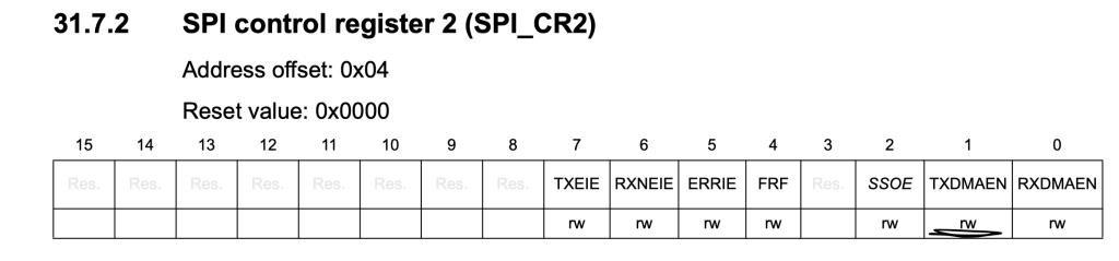
	/*Enable DMATX*/
	SPI1->CR2|=SPI_CR2_TXDMAEN;
Finally, enable the SPI peripheral:
	/*Enable SPI moduel*/
	SPI1->CR1|=SPI_CR1_SPE;
Thats all for SPI. Next, DMA Configuration:
2. DMA Configuration:
First, enable clock access to DMA.
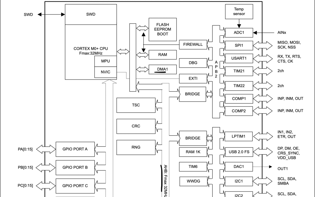
Since STM32L053 has only single DMA and it is connected to AHB Bus, we can enable clock access to DMA1 as following:
	/*Enable clock access to DMA1*/
	RCC->AHBENR|=RCC_AHBENR_DMA1EN;
Now, we need to know which channel and channel selection.
The map request can be found in the reference manual DMA section:
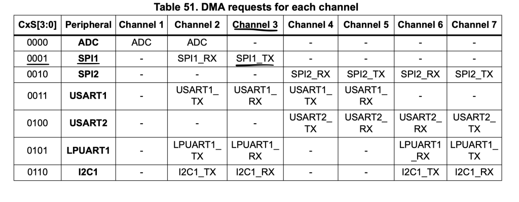
From the request map, the channel 3 and channel selection is 1.
The DMA shall be configured with the following parameters:
- Direct Read from memory.
- Memory increment mode.
- Transfer complete interrupt.
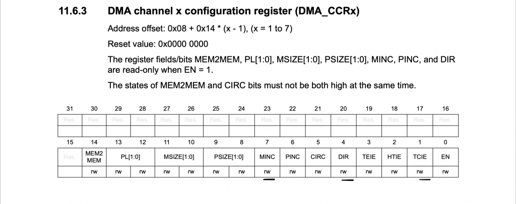
	/*Configure DMA with following parameters
	 * Memory increment mode
	 * Direction: Read from Memory
	 * Transfer complete interrupt
	 * */
	DMA1_Channel3->CCR|=DMA_CCR_MINC|DMA_CCR_DIR|DMA_CCR_TCIE;
Enable the interrupt in NVIC:
	/*Enable the interrupt in NVIC*/
	NVIC_EnableIRQ(DMA1_Channel2_3_IRQn);
Set the peripheral address to be SPI1->DR as following:
	/*Set the peripheral address*/
	DMA1_Channel3->CPAR =(uint32_t)&SPI1->DR;
Set channel 3 selection to be 1:
Since this register doesn’t exist in the header, we shall create it as following:
#define DMA_CSELR (*(volatile unsigned int *)(0x400200a8))
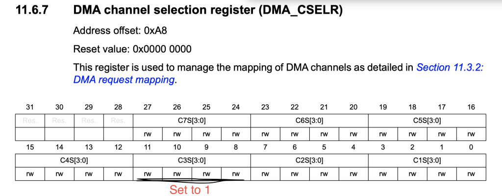
	/*Set the channel selection*/
	DMA_CSELR|=(0x01<<8);
Thats all for the spi_dma_init function.
For interrupt handler:
void DMA1_Channel2_3_IRQHandler()
{

	if(DMA1->ISR & DMA_ISR_TCIF3)
	{
		/*Set tx_done to 1*/
		tx_done=1;
		/*Clear Interrupt flag*/
		DMA1->IFCR =DMA_IFCR_CTCIF3;

		/*Disable DMA*/
		DMA1_Channel3->CCR&=~DMA_CCR_EN;

	}

}
Check if the source is transfer complete from channel 3, if it is:
- Set tx_done to 1.
- Clear the pending interrupt flag.
- Disable the DMA channel.
Check the status:
uint8_t tx_status()
{
	if(tx_done==0){return TX_Inprogress;}
	else {return Tx_Done;}
}
3. SPI DMA transfer function:
The following are the steps required to transfer data over spi:
- Reset tx_done flag.
- Set the memory address to be the array passed as argument.
- Set number of transfer.
- Clear the interrupt flag.
- Launch the DMA.
void spi1_tx_dma(uint8_t * data, uint16_t len)
{
	/*Reset Tx flag*/
	tx_done=0;

	/*Set the memory address to be data*/
	DMA1_Channel3->CMAR=(uint32_t)&data[0];

	/*Set the length*/
	DMA1_Channel3->CNDTR=len;

	/*Clear Interrupt flag*/
	DMA1->IFCR =DMA_IFCR_CTCIF3;

	DMA1_Channel3->CCR|=DMA_CCR_EN;

}
That all for TX function.
In main.c:
#include "spi.h"
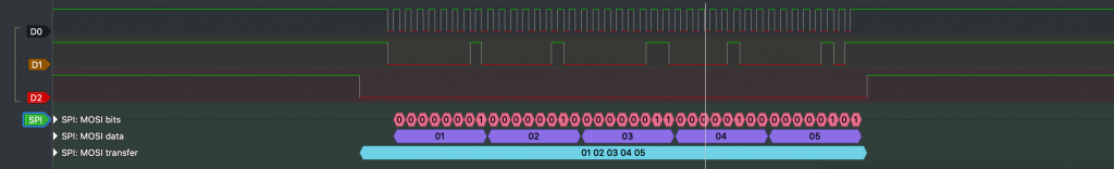
uint8_t data[5]={0x01,0x02,0x03,0x04,0x05};
int main(void)
{
spi_dma_init();
while(1)
{
cs_low();
spi1_tx_dma(data,5);
while(tx_status()==TX_Inprogress);
cs_high();
/*Delay a little bit*/
for (int i=0;i<10000;i++);
}
}4. Code:
You may download the source code from here:
5. Results:
When you connect logic analyzer to PA5, PA7 and PA0, you will get the following results:
Happy coding 🙂
Add Comment