
In the previous guide (here), we saw how to configure timer to work in encoder mode. In this guide, we shall take it step further and measure the rotational speed in RPM (Revolutions per Minutes).
In this guide, we shall cover the following:
- How to measure RPM.
- Proposed experiment.
- Firmware development.
- Code.
- Demo.
1. How to Measure RPM:
Since the encoder is used to measure the RPM, a timer which will overflow each 1 sec to determine the RPM.
Here is a graphic representation:
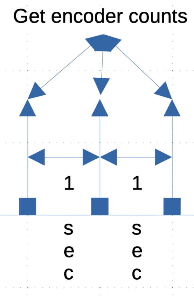
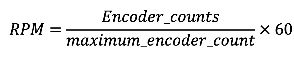
Since the measurements occur each 1 second, we can find RPM as following:
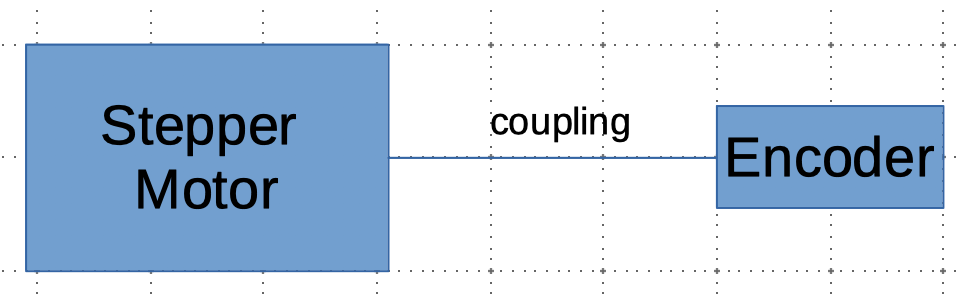
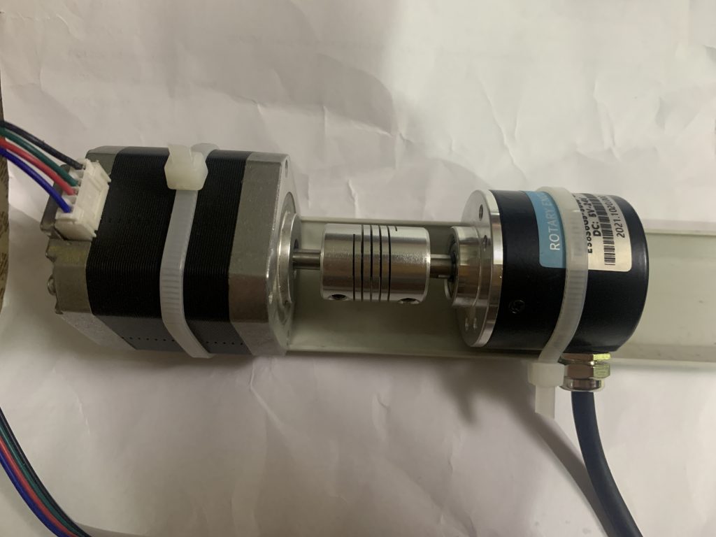
2. Proposed Experiment:
In order to test the code, a crude is conducted which includes the following components:
- Stepper Motor NEMA17 (42HD2037)
- Industrial Rotary encoder (LPD3806-360BM-G5-24C)
- Coupling (6mm-6mm)
3. Firmware development:
Since timer3 is used to determine the encoder counts, we shall use tim5 to generate interrupt each 1 second and timer2 to control the stepper motor.
Since the timer in encoder is already discussed, we shall implement it here differently, we shall use timer3 and pins PB4 and PB5 as inputs for the timer.
First, within rpm_encoder header, declare the following enums:
typedef enum
{
no_new_rpm=0,
new_rpm=1
}rpm_data;

typedef enum
{
ClockWise=0,
CounterClockWise=1
}rpm_dir;
Also, declare the following function:
void Encoder_init(uint16_t max_count);
float get_rpm();
uint8_t new_rpm_available();
uint8_t get_direction();
Hence, the entire header file as following:
#ifndef RPM_ENCODER_H_
#define RPM_ENCODER_H_


typedef enum
{
no_new_rpm=0,
new_rpm=1
}rpm_data;

typedef enum
{
ClockWise=0,
CounterClockWise=1
}rpm_dir;

void Encoder_init(uint16_t max_count);
float get_rpm();
uint8_t new_rpm_available();
uint8_t get_direction();


#endif /* RPM_ENCODER_H_ */
Hence the initializing the encoder mode as following:
void Encoder_init(uint16_t max_count)
	{
	RCC->APB1ENR|=RCC_APB1ENR_TIM3EN;
	RCC->AHB1ENR|=RCC_AHB1ENR_GPIOBEN;
	encoder_counts=max_count;
	/*GPIO B configuration for timer mode */
	GPIOB->MODER|=GPIO_MODER_MODE4_1|GPIO_MODER_MODE5_1;
	GPIOB->MODER&=~(GPIO_MODER_MODE4_0|GPIO_MODER_MODE5_0);
	GPIOB->AFR[0]|=(AF02<<16)|(AF02<<20);

	/*Timer configuration for encoder mode */
	TIM3->ARR = 0xFFFF; //set the max count
	/*Timer in encoder mode*/
	TIM3->CCMR1 |= (TIM_CCMR1_CC1S_0 | TIM_CCMR1_CC2S_0 );
	TIM3->CCER &= ~(TIM_CCER_CC1P | TIM_CCER_CC2P);
	TIM3->SMCR |= TIM_SMCR_SMS_0 | TIM_SMCR_SMS_1;

	/*Timer 5 to generate interrupt each 100ms*/

	RCC->APB1ENR|=RCC_APB1ENR_TIM5EN;
	TIM5->PSC=16000-1;
	TIM5->ARR=1000-1;
	TIM5->DIER|=TIM_DIER_UIE;
	NVIC_EnableIRQ(TIM5_IRQn);
	TIM5->CR1|=TIM_CR1_CEN;

	/*Start the timer */
	TIM3->CR1|=TIM_CR1_CEN;

	}
For the interrupt handler of TIM5:
Within the interrupt handler, we shall determine the direction by check DIR bit in CR1 of TIM3, if the value is 0 it means clockwise, if it is 1, it means counter clockwise.
void TIM5_IRQHandler(void)
{
	TIM5->SR=0; /*clear the status register*/
	/*Determine the direction
	 * 0-> Clockwise
	 * 1->Counter Clockwise
	 * */
	if((TIM3->CR1 & TIM_CR1_DIR)>>TIM_CR1_DIR_Pos==0)
	{
		direction=ClockWise;
		timer_counter=TIM3->CNT;
		TIM3->CNT=0;
	}
	else
	{
		direction=CounterClockWise;
		timer_counter=0xFFFF-TIM3->CNT;
		TIM3->CNT=0xFFFF;
	}

	rpm_new_data=new_rpm;
}
To check in main application if there is new data, we shall simply check rpm_new_data if it is 1 or not as following:
uint8_t new_rpm_available()
{
	uint8_t return_data;
	if(rpm_new_data==new_rpm){return_data=new_rpm;}
	else {return_data=no_new_rpm;}
	return return_data;

}
To calculate the RPM, we shall use the equation above to determine the RPM as following:
float get_rpm()
{
	rpm_new_data=no_new_rpm;
	rpm=(float)(((float)timer_counter)/(float)encoder_counts)*(float)60.0;
	return rpm;
}
Also, we can get the direction as following:
uint8_t get_direction()
{

	return direction;
}
Hence, the entire revised encoder code as following:
#include "stm32f4xx.h"
#include "stdint.h"
#include "RPM_Encoder.h"
#include "delay.h"
const int AF02=0x02;
uint32_t encoder_counts;
float rpm;
uint32_t timer_counter;
volatile uint8_t rpm_new_data,direction;

void Encoder_init(uint16_t max_count)
	{
	RCC->APB1ENR|=RCC_APB1ENR_TIM3EN;
	RCC->AHB1ENR|=RCC_AHB1ENR_GPIOBEN;
	encoder_counts=max_count;
	/*GPIO B configuration for timer mode */
	GPIOB->MODER|=GPIO_MODER_MODE4_1|GPIO_MODER_MODE5_1;
	GPIOB->MODER&=~(GPIO_MODER_MODE4_0|GPIO_MODER_MODE5_0);
	GPIOB->AFR[0]|=(AF02<<16)|(AF02<<20);

	/*Timer configuration for encoder mode */
	TIM3->ARR = 0xFFFF; //set the max count
	/*Timer in encoder mode*/
	TIM3->CCMR1 |= (TIM_CCMR1_CC1S_0 | TIM_CCMR1_CC2S_0 );
	TIM3->CCER &= ~(TIM_CCER_CC1P | TIM_CCER_CC2P);
	TIM3->SMCR |= TIM_SMCR_SMS_0 | TIM_SMCR_SMS_1;

	/*Timer 5 to generate interrupt each 100ms*/

	RCC->APB1ENR|=RCC_APB1ENR_TIM5EN;
	TIM5->PSC=16000-1;
	TIM5->ARR=1000-1;
	TIM5->DIER|=TIM_DIER_UIE;
	NVIC_EnableIRQ(TIM5_IRQn);
	TIM5->CR1|=TIM_CR1_CEN;

	/*Start the timer */
	TIM3->CR1|=TIM_CR1_CEN;

	}

float get_rpm()
{
	rpm_new_data=no_new_rpm;
	rpm=(float)(((float)timer_counter)/(float)encoder_counts)*(float)60.0;
	return rpm;
}


uint8_t new_rpm_available()
{
	uint8_t return_data;
	if(rpm_new_data==new_rpm){return_data=new_rpm;}
	else {return_data=no_new_rpm;}
	return return_data;

}

uint8_t get_direction()
{

	return direction;
}


void TIM5_IRQHandler(void)
{
	TIM5->SR=0; /*clear the status register*/
	/*Determine the direction
	 * 0-> Clockwise
	 * 1->Counter Clockwise
	 * */
	if((TIM3->CR1 & TIM_CR1_DIR)>>TIM_CR1_DIR_Pos==0)
	{
		direction=ClockWise;
		timer_counter=TIM3->CNT;
		TIM3->CNT=0;
	}
	else
	{
		direction=CounterClockWise;
		timer_counter=0xFFFF-TIM3->CNT;
		TIM3->CNT=0xFFFF;
	}

	rpm_new_data=new_rpm;
}
Within the main.c file:
#include "stdio.h"
#include "uart.h"
#include "delay.h"
#include "RPM_Encoder.h"
#include "stepper_motor.h"
#include "lcd.h"
#include "i2c.h"
char char_lcd[20];
uint8_t dir=0;
uint64_t previous_millis;
int main(void)
{
	SCB->CPACR |= ((3UL << 10*2)|(3UL << 11*2));
	i2c_init();
	stepper_init(9000);
	systick_init_ms(16000000);
	uart2_rxtx_init(115200,16000000);
	Encoder_init(1440);
	lcd_init();
	stepper_motor_setDirection(Stepper_Clockwise);
	stepper_motor_start();
	while(1)
	{
		if(new_rpm_available()==new_rpm)
		{
			setCursor(0,0);
			lcd_send_string("Current RPM");
			sprintf(char_lcd,"%0.2f        ",get_rpm());
			setCursor(0,1);
			lcd_send_string(char_lcd);
			setCursor(0,2);
			if(get_direction()==ClockWise)
			{
				lcd_send_string("Clockwise        ");
			}
			else
			{
				lcd_send_string("Counter clockwise");
			}
		}

		if(millis()-previous_millis>5000)
		{
			previous_millis=millis();
			dir=!dir;
			stepper_motor_setDirection(dir);

		}

	}
}
4. Code:
For stepper motor driver code, check this guide.
For the LCD using i2c driver, check this guide.
You may download the entire code from here:
5. Demo:
Happy coding 🙂
Add Comment