In the previous guide (here), we took a look how to control 28BYJ-48 stepper Motor. In this guide, we shall see how control NEMA17 stepper motor which is the most used stepper motor in 3D printers, CNC, robots etc.
In this guide, we will cover the following:
- NEMA17 Stepper Motor
- A4988 Stepper Motor Driver
- Connection diagram
- Code
- Demo
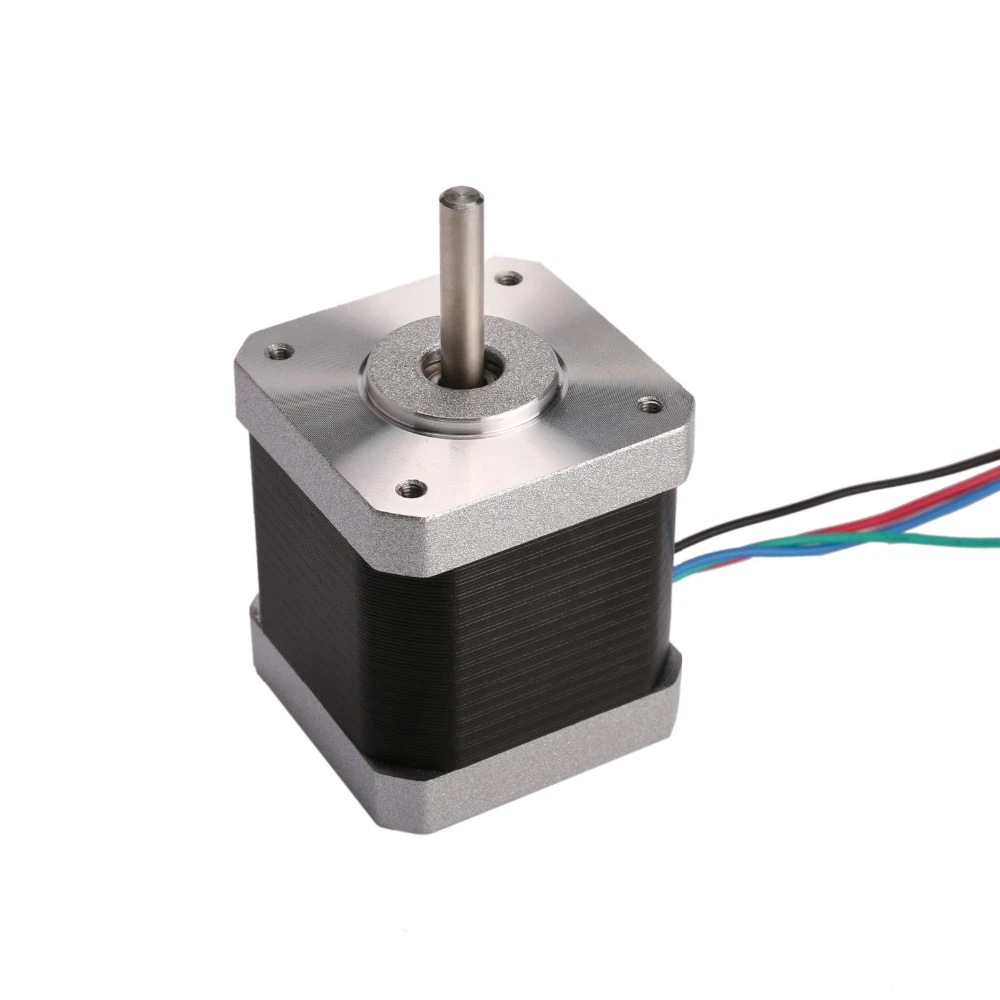
1. NEMA17 Stepper Motor:
NEMA 17 is a hybrid stepping motor with a 1.8° step angle (200 steps/revolution). Each phase draws 1.2 A at 4 V, allowing for a holding torque of 3.2 kg-cm. NEMA 17 Stepper motor is generally used in Printers, CNC machines and Laser Cutters.
Pin Configuration
| NO. | Pin Name | WireColour | Description |
| 1 | Coil 1 | Black | This motor has six wires, connected to two split windings. Black, Yellow, Green wires is part of first winding while Red, White and Blue is part of second winding. |
| 2 | Coil 2 | Yellow | |
| 3 | Coil 3 | Green | |
| 4 | Coil 4 | Red | |
| 5 | Coil 5 | White | |
| 6 | Coil 6 | Blue |
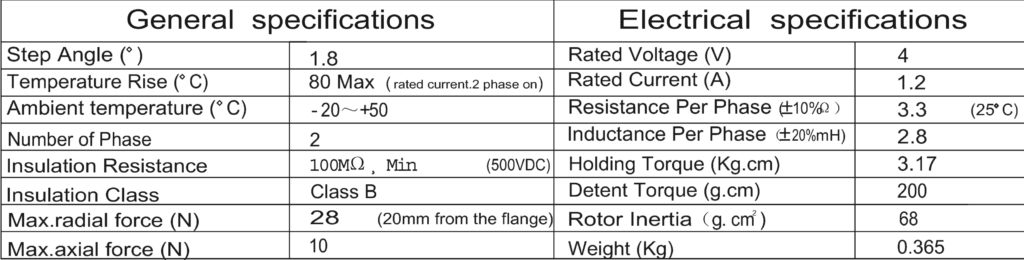
NEMA 17 Stepper Motor Technical Specifications
- Rated Voltage: 12V DC
- Current: 1.2A at 4V
- Step Angle: 1.8 deg.
- No. of Phases: 4
- Motor Length: 1.54 inches
- 4-wire, 8 inch lead
- 200 steps per revolution, 1.8 degrees
- Operating Temperature: -10 to 40 °C
- Unipolar Holding Torque: 22.2 oz-in
2. A4988 Stepper Motor driver
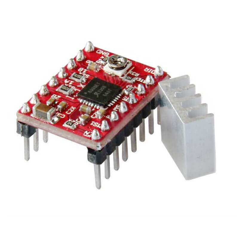
The A4988 is a complete microstepping motor driver with built-in translator for easy operation. It is designed to operate bipolar stepper motors in full-, half-, quarter-, eighth-, and sixteenth-step modes, with an output drive capacity of up to 35 V and ±2 A. The A4988 includes a fixed off-time current regulator which has the ability to operate in slow or mixed decay modes.
The translator is the key to the easy implementation of the A4988. Simply inputting one pulse on the STEP input drives the motor one microstep. There are no phase sequence tables, high frequency control lines, or complex interfaces to program. The A4988 interface is an ideal fit for applications where a complex microprocessor is unavailable or is overburdened.
Top Features
- Low RDS(ON) outputs
- Automatic current decay mode detection/selection
- Mixed and Slow current decay modes
- Synchronous rectification for low power dissipation
- Internal UVLO
- Crossover-current protection
- 3.3 and 5 V compatible logic supply
- Thermal shutdown circuitry
- Short-to-ground protection
- Shorted load protection
- Five selectable step modes: full, 1/2, 1/4, 1/8, and 1/16
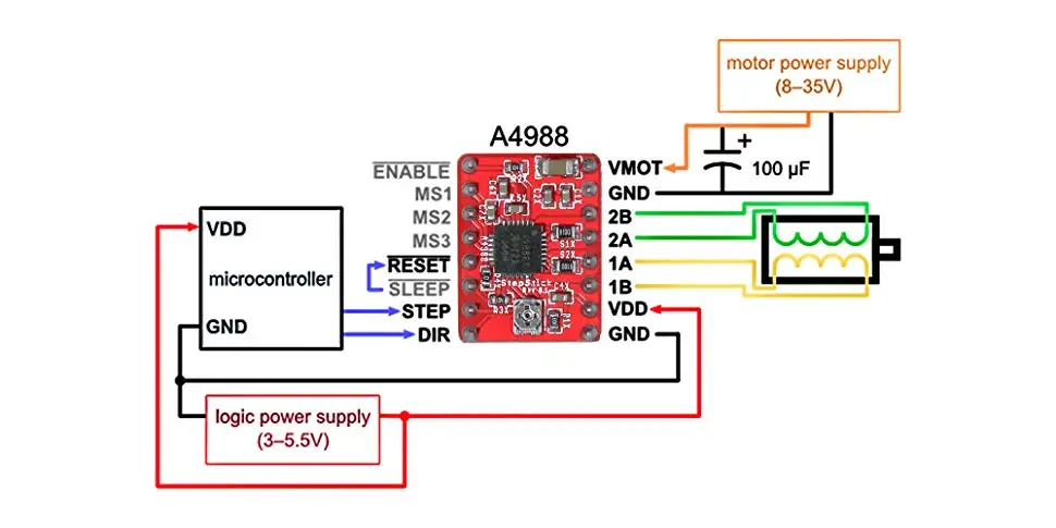
3. Connection Diagram:
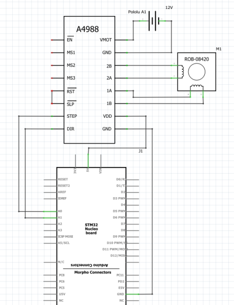
We shall connect STEP pin to PA0 of STM32F411 and the DIR pin to PA1.
4. Code:
We shall set PA0 to generate the PWM signal, for how to configure timer 2 of STM32F411 as PWM, please check this topic (here).
In this guide, we shall change the PWM frequency while maintaining the duty cycle fixed to 50%.
In order to change the frequency of the PWM, the prescaler can be modified during the running of the code
#include "stm32f4xx.h"                  // Device header

int main(void)
	{
	#define TIM2_AF 0x01
	RCC->AHB1ENR	|=	RCC_AHB1ENR_GPIOAEN;
	GPIOA->MODER	|=	GPIO_MODER_MODE0_1;
	GPIOA->MODER	&= ~GPIO_MODER_MODE0_0;
	GPIOA->MODER	|= GPIO_MODER_MODE1_0;
	GPIOA->AFR[0] |= (TIM2_AF<<0);

	RCC->APB1ENR  |=  RCC_APB1ENR_TIM2EN;
	TIM2->CR1     &=~ TIM_CR1_CEN;
	TIM2->CCMR1|=TIM_CCMR1_OC1M_2|TIM_CCMR1_OC1M_1;
	TIM2->CCER|=TIM_CCER_CC1E;
	TIM2->PSC=40000-1;
	TIM2->ARR=10;
	TIM2->CCR1=5;
	TIM2->CR1     |= TIM_CR1_CEN;
	while(1)
				{

					/*change the PWM frequency*/
				for(int i=40000;i>1600;i--)
					{
					TIM2->PSC=i;
					for(int j=0;j<1000;j++);
					}
					/*delay for a little bit*/
					for (int k=0;k<1000000;k++);
					/*disable timer to stop the stepper motor*/
				TIM2->CR1     &=~ TIM_CR1_CEN;
					/*delay for a little bit*/
				for (int k=0;k<1000000;k++){;}
					/*Change the direction*/
				GPIOA->ODR^=GPIO_ODR_OD1;
					/*Enable timer once again*/
				TIM2->CR1     |= TIM_CR1_CEN;
				}
	}
2 Comments
Hello sir
thank you for your sharing
Thank you for sharing, it’s a wonderful article.
Add Comment