In the previous guide (here), we took a look how to configure the UART to receive a character using interrupt and echo back the received character. In this guide, we shall use DMA to recieve data.
In this guide, we shall cover the following:
- Enable DMA for RX in UART.
- Configure the DMA.
- Receive data using DMA.
- Code.
- Results.
1. Enable DMA for RX in UART:
We shall continue from the polling mode from here.
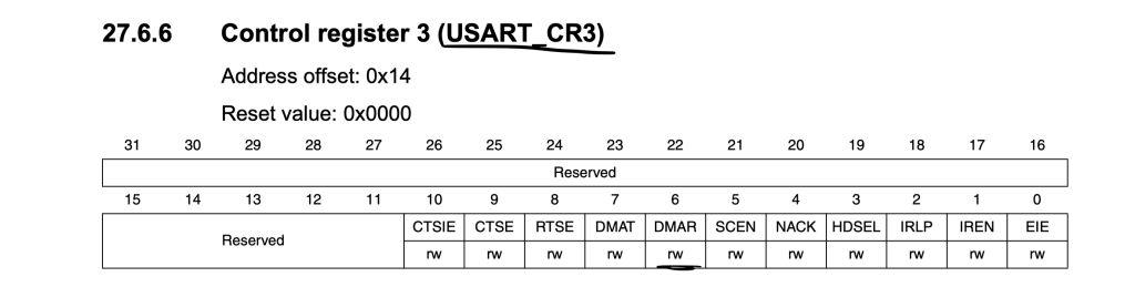
To enable Receiver in DMA mode, we need to set DMAR in CR3 (Control register 3) of USART2 as following:
Make sure that the UART is disable as following :
USART2->CR1 &= ~USART_CR1_UE;
2. Configure the DMA:
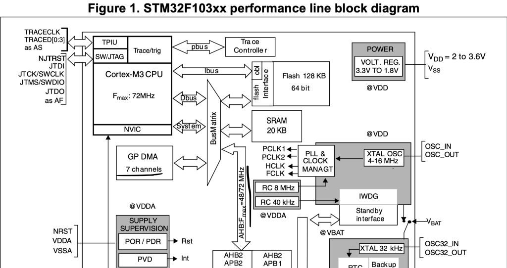
Before we start configuring the DMA, we need to enable clock access to it. To find which bus the DMA is connected to, we need to check the block diagram of STM32F103 in the datasheet which states that DMA is connected to AHB bus:
Hence, we can enable it as following:
RCC->AHBENR|=RCC_AHBENR_DMA1EN;
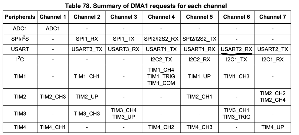
Then we need to know which channel is for UART2_TX, from the reference manual, we can find that channel6 is responsible for USART2_RX:
Hence, the channel shall be configured as following:
- Memory increment mode.
- Direction is read from peripheral.
- Circular mode
- Transfer Complete interrupt.
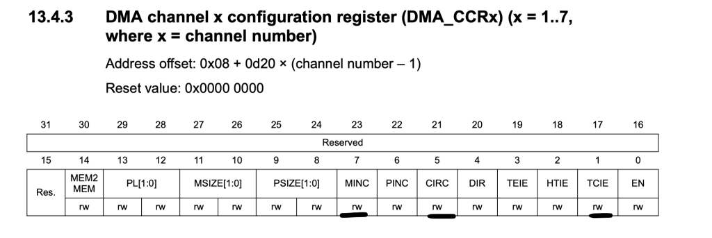
DMA1_Channel6->CCR|=DMA_CCR_MINC|DMA_CCR_CIRC|DMA_CCR_TCIE;
Since we enabled the transfer complete interrupt, we shall enable it in the NVIC also as following:
NVIC_EnableIRQ(DMA1_Channel6_IRQn);
Set the peripheral address to be USART2->DR:
	/*Set the peripheral address to be USART2->DR*/
	DMA1_Channel6->CPAR=(uint32_t)&USART2->DR;
Set the memory address to be the data to be hold:
#define rc_data_size 5
uint8_t rc_data[rc_data_size];

DMA1_Channel6->CMAR=(uint32_t)rc_data;
Number of transfer to be the size of the array:
DMA1_Channel6->CNDTR=rc_data_size;
Enable the DMA channel:
DMA1_Channel6->CCR|=DMA_CCR_EN;
Finally enable the UART:
//Enable UART
USART2->CR1 |= USART_CR1_UE;
For the interrupt handler:
First check if the source transfer completed, if it is true, set done to 1 and clear the pending flag as following:
void DMA1_Channel6_IRQHandler(void)
{
	if(DMA1->ISR &DMA_ISR_TCIF6)
	{
		done=1;
		DMA1->IFCR=DMA_IFCR_CTCIF6;
	}

}
3. Receive Data using DMA:
In while 1 loop, just wait for done to 1 as following:
while(done==0);
Once all characters are received, print them:
printf("Received data:\"%s\"\r\n",rc_data);reset done back to zero:
done=0;
4. Code:
The entire code as following:
#include "stm32f1xx.h"
#include "stdio.h"


#define Perpher_CLK 8000000
#define Baudrate	115200


static uint16_t compute_uart_bd(uint32_t PeriphClk, uint32_t BaudRate)
{
	return ((PeriphClk + (BaudRate/2U))/BaudRate);
}


static void uart_set_baudrate(USART_TypeDef *USARTx, uint32_t PeriphClk,  uint32_t BaudRate)
{
	USARTx->BRR =  compute_uart_bd(PeriphClk,BaudRate);
}


void uart2_write(int ch)
{
  /*Make sure the transmit data register is empty*/
	while(!(USART2->SR & USART_SR_TXE)){}

  /*Write to transmit data register*/
	USART2->DR	=  (ch & 0xFF);
}

/*Retargeting printf*/
int __io_putchar(int ch){uart2_write(ch); return ch;}


#define rc_data_size 5
uint8_t rc_data[rc_data_size];

volatile uint8_t done=0;


int main(void)
{

	/*UART2 Pin configures*/

	//enable clock access to GPIOA
	RCC->APB2ENR|=RCC_APB2ENR_IOPAEN;
	//Enable clock access to alternate function
	RCC->APB2ENR|=RCC_APB2ENR_AFIOEN;

	/*Confgiure PA2 as output maximum speed to 50MHz
	 * and alternate output push-pull mode*/
	GPIOA->CRL|=GPIO_CRL_MODE2;

	GPIOA->CRL|=GPIO_CRL_CNF2_1;
	GPIOA->CRL&=~GPIO_CRL_CNF2_0;


	/*Configure PA3 as Input floating*/

	/*Set mode to be input*/
	GPIOA->CRL &=~(GPIO_CRL_MODE3);
	GPIOA->CRL|=GPIO_CRL_CNF3_0;
	GPIOA->CRL&=~GPIO_CRL_CNF3_1;


	/*Don't remap the pins*/
	AFIO->MAPR&=~AFIO_MAPR_USART2_REMAP;


	/*USART2 configuration*/

	//enable clock access to USART2

	RCC->APB1ENR|=RCC_APB1ENR_USART2EN;

	//Transmit Enable
	USART2->CR1 |= USART_CR1_TE;

	//Enable receiver
	USART2->CR1 |= USART_CR1_RE;


	/*Enable DMA for receiver*/
	USART2->CR3|=USART_CR3_DMAR;

	/*Set baudrate */
	uart_set_baudrate(USART2,Perpher_CLK,Baudrate);

	/*DMA configuration*/

	RCC->AHBENR|=RCC_AHBENR_DMA1EN;

	DMA1_Channel6->CCR|=DMA_CCR_MINC|DMA_CCR_CIRC|DMA_CCR_TCIE;

	NVIC_EnableIRQ(DMA1_Channel6_IRQn);

	/*Set the peripheral address to be USART2->DR*/
	DMA1_Channel6->CPAR=(uint32_t)&USART2->DR;

	DMA1_Channel6->CMAR=(uint32_t)rc_data;

	DMA1_Channel6->CNDTR=rc_data_size;

	DMA1_Channel6->CCR|=DMA_CCR_EN;


	//Enable UART
	USART2->CR1 |= USART_CR1_UE;


	while(1)
	{
		while(done==0);
		printf("Received data:\"%s\"\r\n",rc_data);
		done=0;


	}
}

void DMA1_Channel6_IRQHandler(void)
{
	if(DMA1->ISR &DMA_ISR_TCIF6)
	{
		done=1;
		DMA1->IFCR=DMA_IFCR_CTCIF6;
	}

}
5. Demo:
Happy coding 🙂
Add Comment