
In the previous guide of timer (here), we took a look how to configure the timer in PWM mode. In this guide, we shall use timer in output compare mode to toggle the LED on CH1 of TIM2.
In this guide, we shall cover the following:
- What is output compare mode.
- Configure the timer and GPIO for output compare mode.
- Connection
- Code.
- Demo
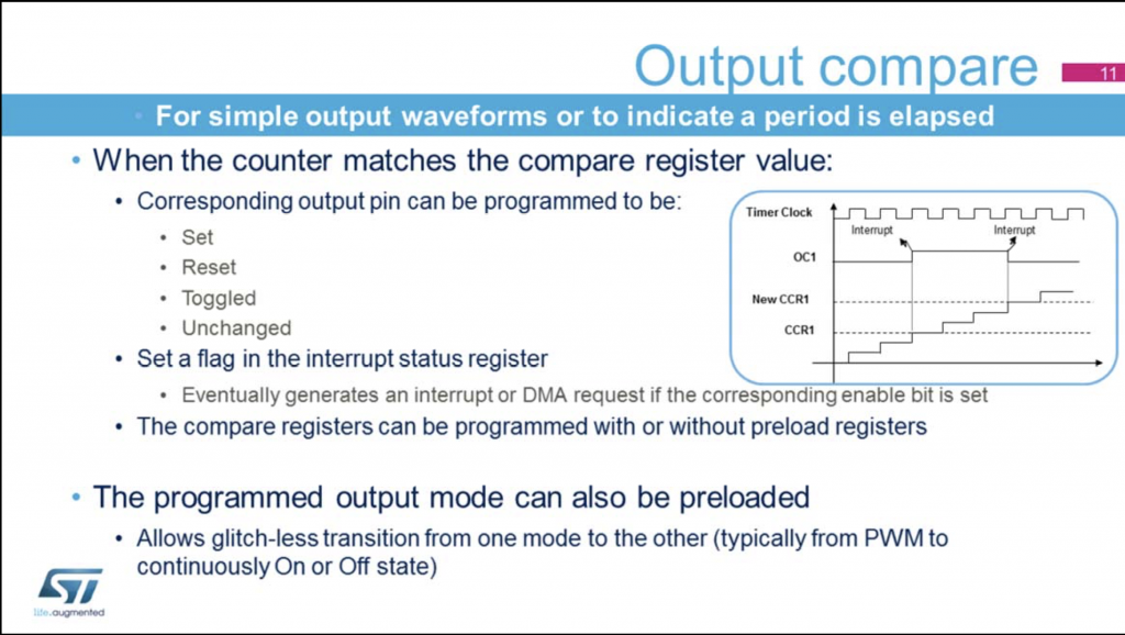
1. What is output compare mode:
In this mode, the timer shall count to the maximum level (set by the ARR), the following will happen:
- Assigns the corresponding output pin to a programmable value defined by the output compare mode.
- Sets a flag in the interrupt status register.
- Generates an interrupt if the corresponding interrupt mask is set.
- Sends a DMA request if the corresponding enable bit is set.
In our case, we will toggle PA0(TIM2_CH1).
2. Configure the timer and GPIO for output compare mode:
First, We need to decide on which timer to use since STM32F1 has multiple timers:
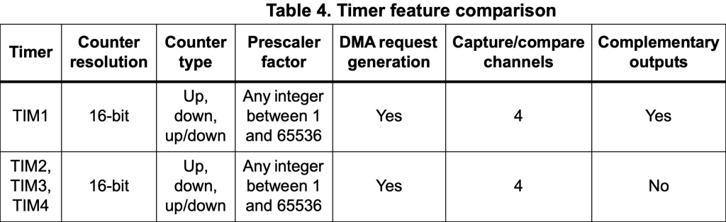
In this guide, we shall use TIM2.
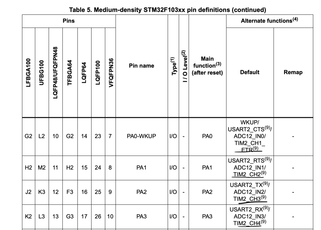
Now, we need to find which pins are connected to TIM2, from the datasheet, we can find that PA0 to PA3 are connected to TIM2_CH1 to TIM2CH4. In this guide, we are interested in TIM2_CH1, hence we need to configure PA0 as following:
- Output mode with maximum speed of 50MHz.
- Alternate Output Push/Pull mode.
First, we need to enable clock access to GPIOA:
RCC->APB2ENR|=RCC_APB2ENR_IOPAEN;
Then configure PA0:
	/*Configure PA0 as Output Alternate Push/Pull */
	GPIOA->CRL|=GPIO_CRL_MODE0;
	GPIOA->CRL|=(GPIO_CRL_CNF0_1);
	GPIOA->CRL&=~(GPIO_CRL_CNF0_0);
Finally, don’t remap to another pins:
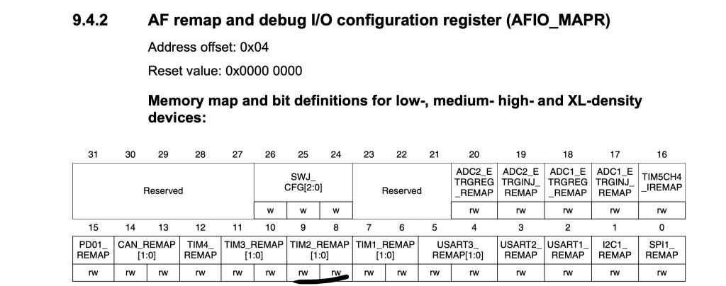
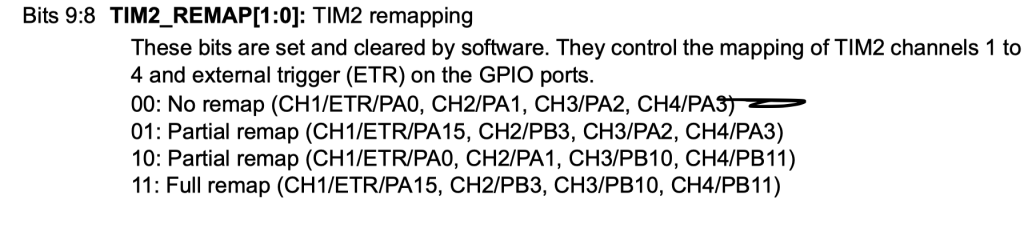
	/*Don't remap the pin*/
	AFIO->MAPR&=~AFIO_MAPR_TIM2_REMAP;
For the timer configuration, first enable clock access to TIM2 as following:
	/*Enable clock access to timer2*/
	RCC->APB1ENR|=RCC_APB1ENR_TIM2EN;
Set the prescaler and ARR to (8000-1) and (1000-1) respectively:
	/*Configure timer2*/
	TIM2->PSC=8000-1;
	TIM2->ARR=1000-1;
Now, in TIMx capture/compare mode register 1 which is responsible for CH1 and CH2, we need to set OC1M in Toggle on Match Mode as following:
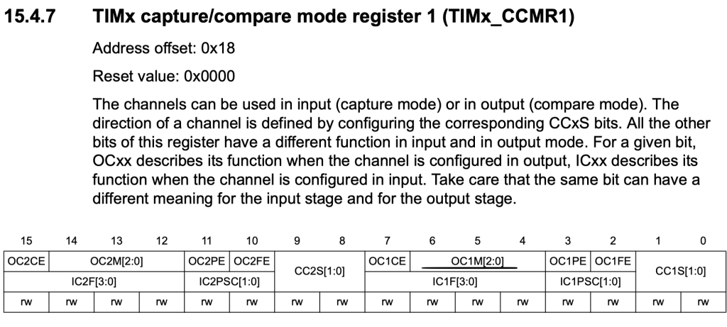
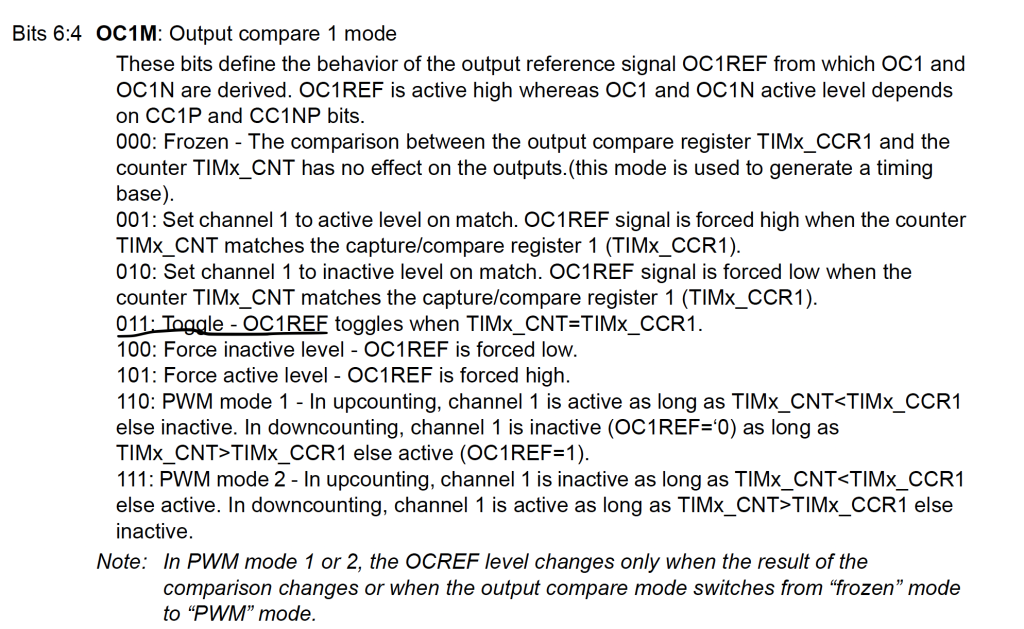
TIM2->CCMR1|=TIM_CCMR1_OC1M_0|TIM_CCMR1_OC1M_1;
hen enable the channel from TIMx capture/compare enable register (TIMx_CCER):
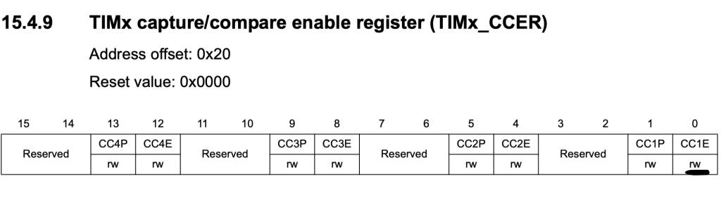
TIM2->CCER|=TIM_CCER_CC1E;
Finally, enable the timer:
TIM2->CR1|=TIM_CR1_CEN;
3. Connection:
The connection as following:
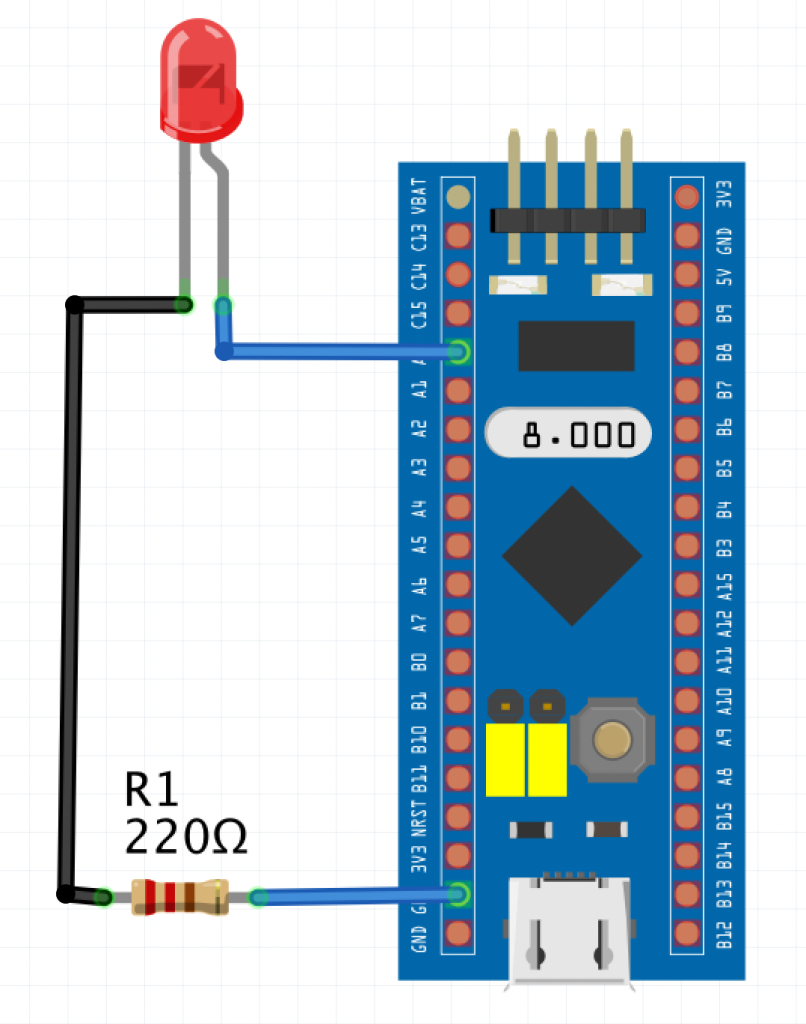
4. Code:
The code as following:
#include "stm32f1xx.h"

int main(void)
{
	RCC->APB2ENR|=RCC_APB2ENR_IOPAEN;

	/*Configure PA0 as Output Alternate Push/Pull */
	GPIOA->CRL|=GPIO_CRL_MODE0;
	GPIOA->CRL|=(GPIO_CRL_CNF0_1);
	GPIOA->CRL&=~(GPIO_CRL_CNF0_0);

	/*Don't remap the pin*/
	AFIO->MAPR&=~AFIO_MAPR_TIM2_REMAP;


	/*Enable clock access to timer2*/
	RCC->APB1ENR|=RCC_APB1ENR_TIM2EN;

	/*Configure timer2*/
	TIM2->PSC=8000-1;
	TIM2->ARR=1000-1;
	TIM2->CCMR1|=TIM_CCMR1_OC1M_0|TIM_CCMR1_OC1M_1;
	TIM2->CCER|=TIM_CCER_CC1E;
	TIM2->CR1|=TIM_CR1_CEN;

	while(1)
	{
	}
}
5. Demo:
Upload the code to your STM32F103 and connected as LED to PA0 as shown in connection section, you should 1 second toggle rate (1 second on and 1 second off).
Add Comment