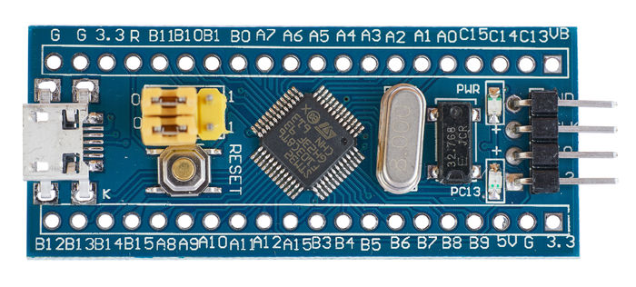
In this new guide series, we shall develop some drivers for the most widely used STM32 which STM32F103 aka bluepill.
In this guide, we shall cover the following:
- Setting up the environment
- Getting the required documents.
- Developing GPIO output driver.
- Code.
- Demo.
1. Setting up the environment:
To setup the environment, please refer to the following topic here.
Just modify it for STM32F103.
For the symbols, use the following:
STM32F103xB
2. Getting the required documents:
First document needed is the datasheet.
You can get the datasheet from here.
Also, you need the reference manual from here.
3. Developing GPIO Output Driver:
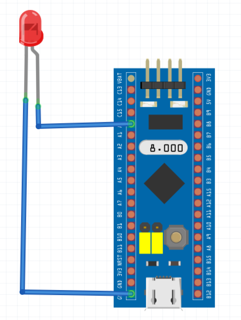
Since the guide uses external LED, we shall use GPIOA pin 0 to blink the LED. The connection the LED to STM32F103 as following:
Since the LED is connected to Port A, we need to enable clock access to GPIO. From the datasheet, we can find the block diagram:
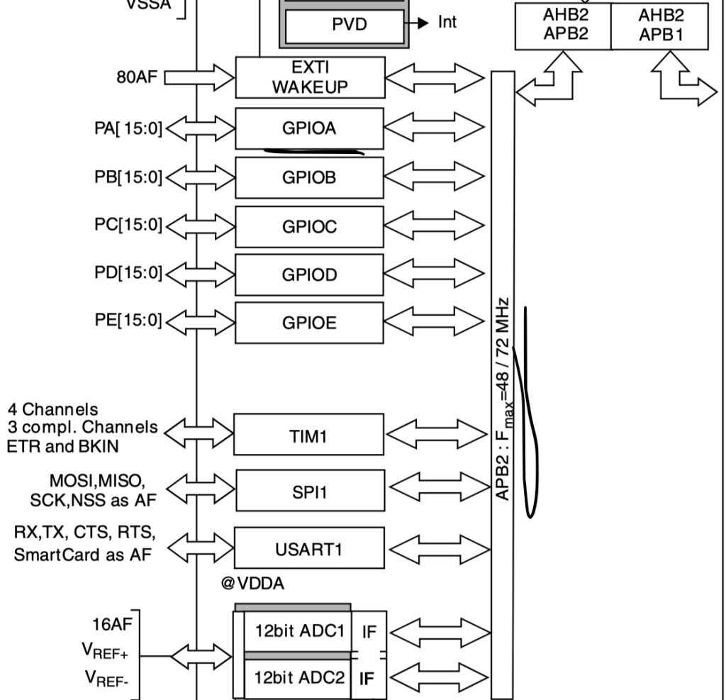
Since GPIOA is connected to APB2 bus, we can enable clock access to GPIOA from RCC_APB2ENR register:
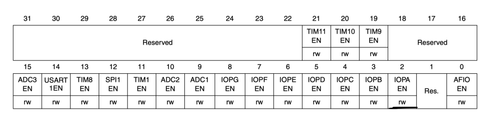
RCC->APB2ENR|=RCC_APB2ENR_IOPAEN;
Then GPIO configuration:
Since the LED is connected to PA0, we need to use Port configuration register low (CRL) which can configure pins from 0 to 7 while Port configuration register high (CRH) configure pins from 8 to 15.
First thing we need the following:
- Configure the pin as Output with maximum speed of 50MHz.
- Set the output mode to be output push-pull.
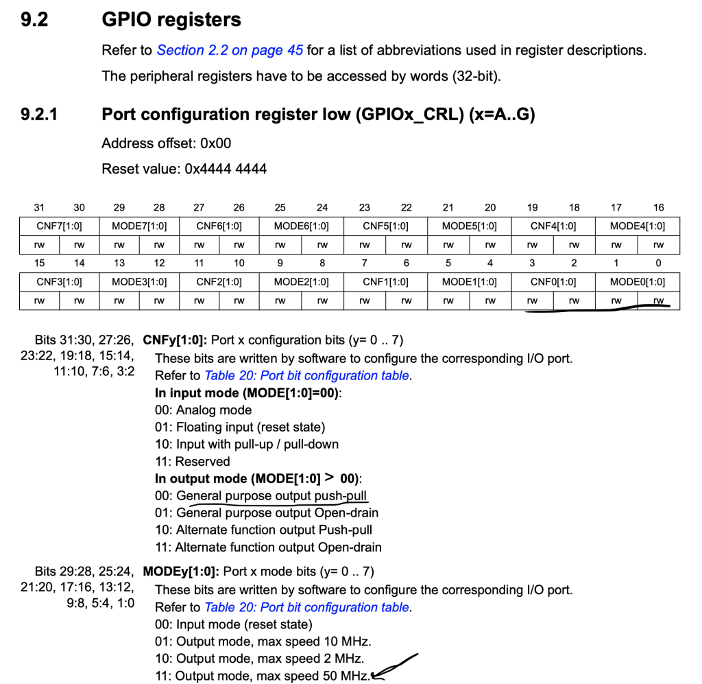
Hence, we need to set bit 0 and 1 to 1 (MODE0) and bit 2 and 3 to 0 (CNF0).
We shall use macros offered by STM32F1 header file
GPIOA->CRL|=GPIO_CRL_MODE0;
	GPIOA->CRL&=~(GPIO_CRL_CNF0);
Then we need to use BSRR register to set and reset the bit:
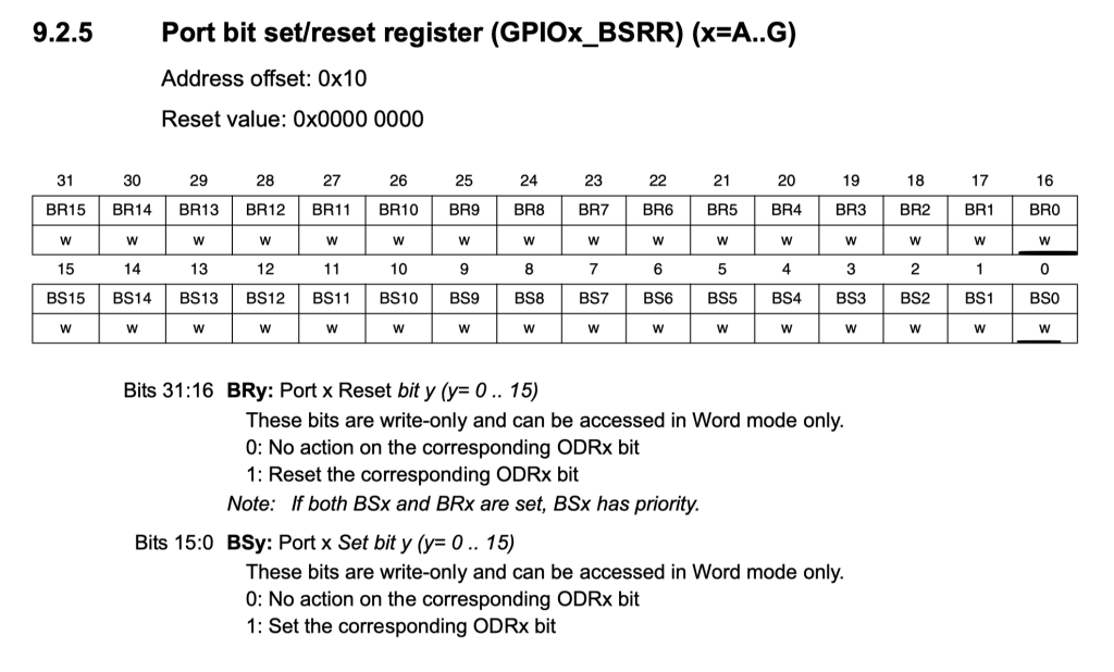
		GPIOA->BSRR=GPIO_BSRR_BS0;
		for(int i=0;i<100000;i++);/*Delay*/
		GPIOA->BSRR=GPIO_BSRR_BR0;
		for(int i=0;i<100000;i++);/*Delay*/
Hence, the code as following:
#include "stm32f1xx.h"


int main(void)
{
	RCC->APB2ENR|=RCC_APB2ENR_IOPAEN;
	GPIOA->CRL|=GPIO_CRL_MODE0;
	GPIOA->CRL&=~(GPIO_CRL_CNF0);

	while(1)
	{
		GPIOA->BSRR=GPIO_BSRR_BS0;
		for(int i=0;i<100000;i++);/*Delay*/
		GPIOA->BSRR=GPIO_BSRR_BR0;
		for(int i=0;i<100000;i++);/*Delay*/


	}
}
4. Code:
You may download the code from here:
5. Demo:
Happy coding 🙂
Add Comment