In the previous guide (here), we saw how to configure the uart to receive single character. In this guide, we shall use DMA to transmit data over UART.
In this guide, we shall cover the following:
- UART Configuration for DMA in TX Mode.
- DMA Configuration.
- UART TX in DMA mode function
- Code.
- Results
1. UART Configuration for DMA in TX Mode:
We start from part one (here), Now, we need to enable DMATX for the USART3. In order to enable it, we need to set bit DMAT in CR3:
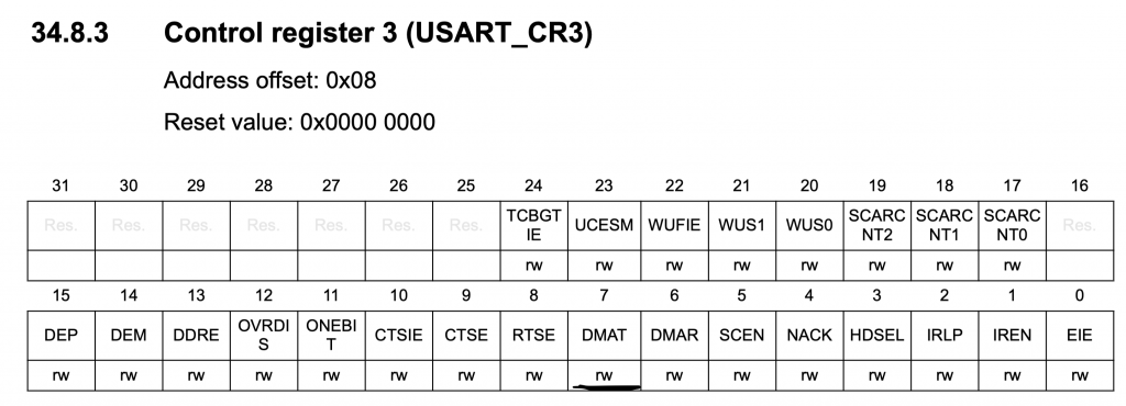
USART3->CR3|=USART_CR3_DMAT;
2. DMA Configuration:
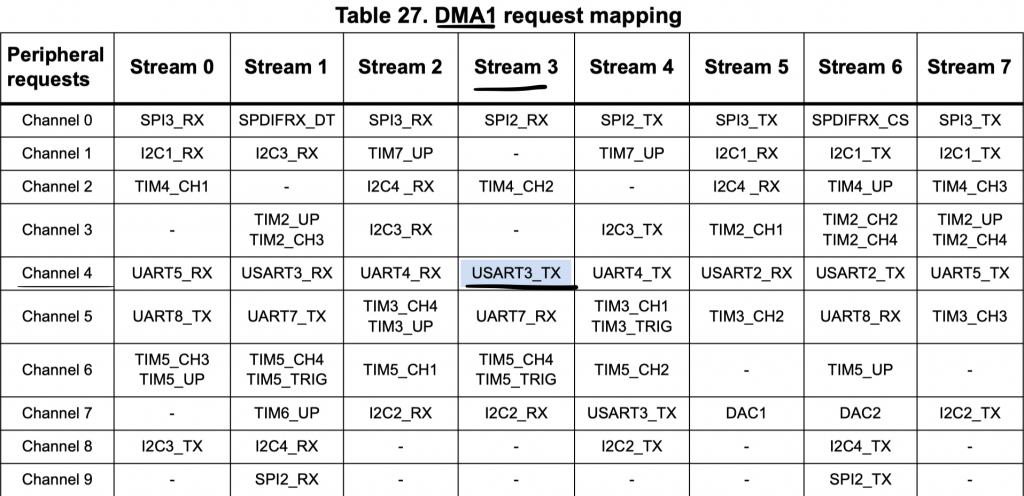
In order to check with DMA, Stream and channel needed for the USART, we need to check the DMA request mapping within the reference manual of STM32F767.
We can see that DMA1 Stream3 Channel4 is responsible for USART3_TX, hence we shall use DMA1_Stream3 channel 4 in this guide.
We start configuring the DMA1 as following:
Enable clock access to DMA1:
RCC->AHB1ENR|=RCC_AHB1ENR_DMA1EN;
Make disable the stream and make sure it is disabled:
	DMA1_Stream3->CR &=~(DMA_SxCR_EN);
	while((DMA1_Stream3->CR &(DMA_SxCR_EN)));
Configure the DMA as following:
- Channel 4.
- Memory to Peripheral.
- Memory increment mode.
- Transfer complete interrupt.
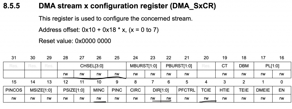
#define ch4 0x04
DMA1_Stream3->CR|=(ch4<<25)|DMA_SxCR_MINC|DMA_SxCR_DIR_0|DMA_SxCR_TCIE;
Set the peripheral address to TDR register of USART3 as following:
DMA1_Stream3->PAR=(uint32_t)&USART3->TDR;
Enable the interrupt in NVIC controller:
NVIC_EnableIRQ(DMA1_Stream3_IRQn);
for the interrupt handler:
We check if the source is transfer complete interrupt from channel3 and set tx_finished to 1 then clear the pending interrupt.
void DMA1_Stream3_IRQHandler(void)
	{
		if(DMA1->LISR & DMA_LISR_TCIF3)
			{
				tx_finished=1;
				DMA1->LIFCR=DMA_LIFCR_CTCIF3;
			}

	}
3. UART TX in DMA Mode:
We start of by declaring a function thats will take two arguments:
- Pointer to the data that hold the data to be transmitted.
- Length of the data to be transmitted.
void usart_dma_write(char *data, uint16_t length)
Within the function, we shall set the memory of DMA1 to the data buffer:
DMA1_Stream3->M0AR= data;
The length to be the length passed to the function:
DMA1_Stream3->NDTR=length;
Start the stream:
DMA1_Stream3->CR|=DMA_SxCR_EN;
Wait until the transfer is completed (depending on your application):
while(tx_finished==0);
tx_finished=0;
4. Code:
In main.c file, we shall use counter to be displayed:
#include "uart.h"
#include "stm32f7xx.h"


char uart_data_tx[40];
uint8_t counter=0;
uint8_t length;
void delay(int ms)
{
	int i;
	SysTick->LOAD=16000-1;
	SysTick->VAL=0;
	SysTick->CTRL=0x5;
		for ( i=0;i<ms;i++)
		{
			while(!(SysTick->CTRL &0x10000)){}
		}
	SysTick->CTRL=0;

}


int main(void)
	{
		uart_tx_dma_init();
		while(1)
			{
				length=sprintf(uart_data_tx,"Counter value = %d\r\n",counter++);
				usart_dma_write(uart_data_tx,length);
				delay(200);
			}


	}
You may download the code from here:
5. Results:
After you compile and upload the code to your Nucleo-144 F767, open serial terminal and set the baudrate to be 115200 and you will see this:
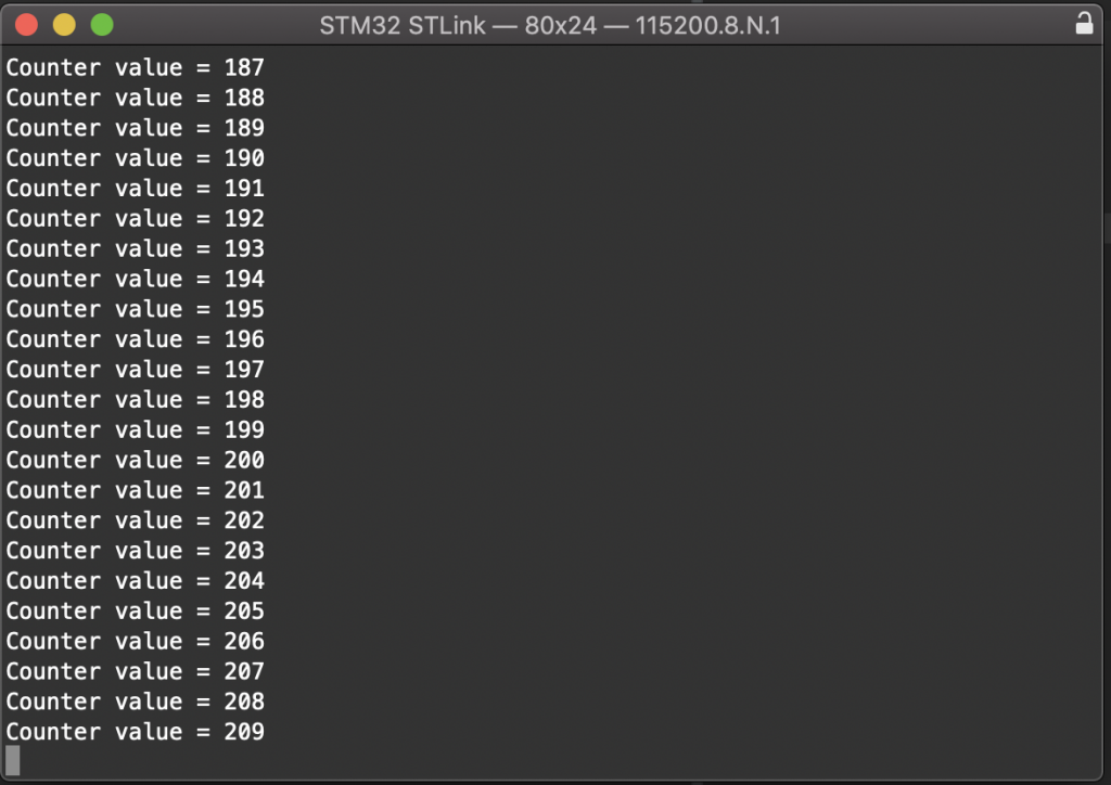
Happy coding 🙂
Add Comment