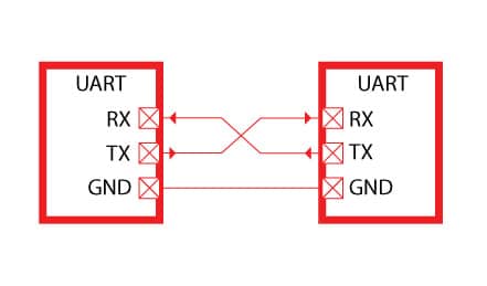
In the previous guide (here), we took a look how to configure the PD8 to work as USART3 TX. In this guide, we shall use PD9 to receive characters over UART and echo back the received characters.
In this guide, we shall cover the following:
- Configure pin and UART
- Code
- Demo
1.1 Configure pin and UART:
From the pervious, we enabled UART and GPIOD clock access. In order to add the RX functionality, we should set PD9.
In order to set PD9 to act as UART3_RX, we need to set it as alternate function and select alternate function 7 as following:
#define AF07 0x07

GPIOD->MODER|=GPIO_MODER_MODER9_1;//set PD9 as alternate function

GPIOD->AFR[1]|=(AF07<<4); //selecting the alternate fuction
Now, for configuring the UART, we need to enable RX part from control register 1 (CR1)
USART3->CR1|=USART_CR1_RE; //enbale RX
Hence the initializing sequence is as follow:
		#define AF07 0x07
		//Configure GPIOD PD8 as TX pin
		RCC->AHB1ENR|=RCC_AHB1ENR_GPIODEN;
		GPIOD->MODER|=GPIO_MODER_MODER8_1;

		GPIOD->AFR[1]|=(AF07<<0);
		//configure GPIOD PD9 as RX pin
		GPIOD->MODER|=GPIO_MODER_MODER9_1;
		GPIOD->AFR[1]|=(AF07<<4);

		//Configure the UART

		RCC->APB1ENR|=RCC_APB1ENR_USART3EN;
		USART3->BRR    = 0x008B; // baud rate 115200 @16MHz
		USART3->CR1    = 0; // Enable Tx and Rx and Enable USART2
		USART3->CR1|=USART_CR1_TE; //enbale TX
		USART3->CR1|=USART_CR1_RE; //enbale RX
		USART3->CR1|=USART_CR1_UE; //enable UART
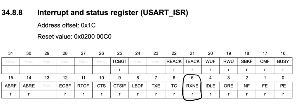
1.2 Checking for availability of the data:
We can check for the data availability bit 5 (RXNE) from Interrupt and status register (USART_ISR) as following
int uart3_available(void)
{
if((USART3->ISR)&USART_ISR_RXNE){return 1;}
else {return 0;}
}
if the serial has new data, we can read it as following
//read the RX buffer
unsigned char uart3_read(void)
{
return USART3->RDR;
}
2. Code:
The code for receiving a character and echo back
#include "stm32f7xx.h"                  // Device header

//PD8 for USART3 TX

void uart3_write(unsigned char x)
{

USART3->TDR =(x);
while(!((USART3->ISR)&USART_ISR_TC)){;}
}
//if there is data in the buffer
int uart3_available(void)
{
if((USART3->ISR)&USART_ISR_RXNE){return 1;}
else {return 0;}

}
//read the RX buffer
unsigned char uart3_read(void)
{
return USART3->RDR;
}


int main(void)
	{
		#define AF07 0x07
		//Configure GPIOD PD8 as TX pin
		RCC->AHB1ENR|=RCC_AHB1ENR_GPIODEN;
		GPIOD->MODER|=GPIO_MODER_MODER8_1;

		GPIOD->AFR[1]|=(AF07<<0);
		//configure GPIOD PD9 as RX pin
		GPIOD->MODER|=GPIO_MODER_MODER9_1;
		GPIOD->AFR[1]|=(AF07<<4);

		//Configure the UART

		RCC->APB1ENR|=RCC_APB1ENR_USART3EN;
		USART3->BRR    = 0x008B; // baud rate 115200 @16MHz
		USART3->CR1    = 0; // Enable Tx and Rx and Enable USART2
		USART3->CR1|=USART_CR1_TE; //enbale TX
		USART3->CR1|=USART_CR1_RE; //enbale RX
		USART3->CR1|=USART_CR1_UE; //enable UART

	while(1)
	{
		if(uart3_available()) //if there is new data
				{
				uart3_write(uart3_read()); //read and send it back
				}
	}
	}
Add Comment