In the previous guide (here), we saw how to configure the UART and DMA to work in transmit mode. In this guide, we shall see how to configure the DMA and UART to work in full duplex.
In this guide, we shall cover the following:
- Configure UART in DMA Full duplex.
- Configure the DMA to receive data from UART.
- Code.
- Demo.
1. Configure UART in DMA Full Duplex:
First thing first, enable clock access to GPIOA and set PA2 and PA3 to alternate function and set the alternate function to AF4 (from here):
	RCC->IOPENR |= RCC_IOPENR_GPIOAEN;
	GPIOA->MODER|=GPIO_MODER_MODE2_1;
	GPIOA->MODER&=~GPIO_MODER_MODE2_0;

	GPIOA->MODER|=GPIO_MODER_MODE3_1;
	GPIOA->MODER&=~GPIO_MODER_MODE3_0;

	#define AF04 0x04
	GPIOA->AFR[0]|=(AF04<<8);
	GPIOA->AFR[0]|=(AF04<<12);
Then enable clock access to USART2 as following:
RCC->APB1ENR |= RCC_APB1ENR_USART2EN;
Set the desired baudrate:
USART2->BRR=compute_uart_bd(APB1_CLK,UART_BAUDRATE);
Enable both direction for UART:
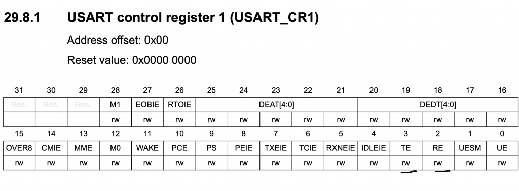
	/*Configure transfer direction*/
	USART2->CR1 = USART_CR1_TE|USART_CR1_RE;
Enable DMAT and DMAR in CR3 (Control Register 3):
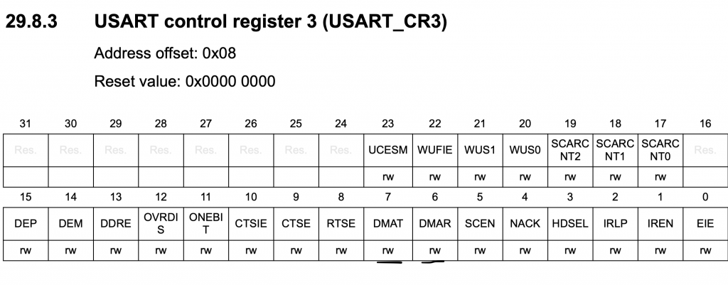
 	/*Enable DMA TX & RX for UART*/
	USART2->CR3|=USART_CR3_DMAT|USART_CR3_DMAR;
Finally enable the UART moduel:
	/*Enable uart module*/
	USART2->CR1 |= USART_CR1_UE;
2. Configure the DMA to Receive Data from UART:
We start off by enabling clock access to DMA1:
	/*Enable Clock access to DMA1*/
	RCC->AHBENR|=RCC_AHBENR_DMA1EN;
From the previous guide, we noticed that DMA1_Channel6 is for USART2_RX. Hence, we can this for the USART2_RX.
We start off by disabling the DMA1_Channel6 as following:
	DMA1_Channel6->CCR&=~DMA_CCR_EN;
	while((DMA1_Channel6->CCR &DMA_CCR_EN));
Then configure the DMA as following:
- Memory increment.
- Circular mode.
- Transfer completed interrupt.
- Enable the interrupt in NVIC.
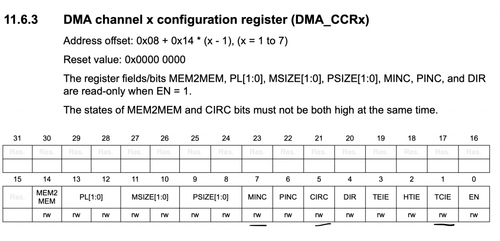
	DMA1_Channel6->CCR|=DMA_CCR_MINC|DMA_CCR_CIRC|DMA_CCR_TCIE;
	NVIC_EnableIRQ(DMA1_Channel4_5_6_7_IRQn);
Set the peripheral address to USART2->RDR:
DMA1_Channel6->CPAR=(uint32_t)(&USART2->RDR);
Set channel 6 to USART2:
DMA_CSELR|=(0x04<<20);
Set the memory address to the buffer:
DMA1_Channel6->CMAR=(uint32_t)data_rx;
Set number of transfer to 5:
DMA1_Channel6->CNDTR=5;
Enable the DMA_Channel6:
DMA1_Channel6->CCR|=DMA_CCR_EN;
For the interrupt handler:
void DMA1_Channel4_7_IRQHandler(void)
	{

		if(DMA1->ISR & DMA_ISR_TCIF7)
			{
				inprogress=0;
				DMA1->IFCR|=DMA_IFCR_CTCIF7;
			}
		if(DMA1->ISR & DMA_ISR_TCIF6)
			{
				received=1;
				DMA1->IFCR|=DMA_IFCR_CTCIF6;
			}
		NVIC_ClearPendingIRQ(DMA1_Channel4_5_6_7_IRQn);
	}
3. Code:
Hence, the entire Full-Duplex code as following:
#include "stm32l0xx.h"
#include "stdio.h"
#define SYS_FREQ		2097000
#define APB1_CLK		SYS_FREQ

#define UART_BAUDRATE	115200

volatile uint8_t received=0, inprogress=0;


char data_tx[40];
char data_rx[5];
uint16_t length;


#define DMA_CSELR  (*(volatile unsigned int *)(0x400200a8))


static uint16_t compute_uart_bd(uint32_t PeriphClk, uint32_t BaudRate)
{
	return ((PeriphClk  +  (BaudRate/2U))/BaudRate);
}


void uart_transmit_dma(char *message, uint16_t len)
	{

		if(inprogress==0)
		{
			/*DMA1 Channel 7 is for USART_TX*/
			DMA1_Channel7->CCR &=~DMA_CCR_EN;

			while((DMA1_Channel7->CCR &DMA_CCR_EN));
			DMA1_Channel7->CCR|=DMA_CCR_MINC|DMA_CCR_DIR|DMA_CCR_TCIE;
			NVIC_EnableIRQ(DMA1_Channel4_5_6_7_IRQn);
			DMA1_Channel7->CPAR=(uint32_t)(&USART2->TDR);
			DMA_CSELR|=(0x04<<24);
			DMA1->IFCR|=DMA_IFCR_CTCIF7;
			DMA1_Channel7->CMAR=(uint32_t)message;
			DMA1_Channel7->CNDTR=(uint16_t)len;
			DMA1_Channel7->CCR|=DMA_CCR_EN;
			inprogress=1;
		}
		else return;
	}


int main(void)
{
	/*Enable clock access to GPIOA*/
	RCC->IOPENR |= RCC_IOPENR_GPIOAEN;
	GPIOA->MODER|=GPIO_MODER_MODE2_1;
	GPIOA->MODER&=~GPIO_MODER_MODE2_0;

	GPIOA->MODER|=GPIO_MODER_MODE3_1;
	GPIOA->MODER&=~GPIO_MODER_MODE3_0;

	#define AF04 0x04
	GPIOA->AFR[0]|=(AF04<<8);
	GPIOA->AFR[0]|=(AF04<<12);


	RCC->APB1ENR |= RCC_APB1ENR_USART2EN;
	USART2->BRR=compute_uart_bd(APB1_CLK,UART_BAUDRATE);
	/*Configure transfer direction*/
	USART2->CR1 = USART_CR1_TE|USART_CR1_RE;
	/*Enable DMA TX & RX for UART*/
	USART2->CR3|=USART_CR3_DMAT|USART_CR3_DMAR;
	/*Enable uart module*/
	USART2->CR1 |= USART_CR1_UE;

	/*Enable Clock access to DMA1*/
	RCC->AHBENR|=RCC_AHBENR_DMA1EN;

	/*Configure DMA1_Channel6 for USART2_RX*/
	DMA1_Channel6->CCR&=~DMA_CCR_EN;
	while((DMA1_Channel6->CCR &DMA_CCR_EN));
	DMA1_Channel6->CCR|=DMA_CCR_MINC|DMA_CCR_CIRC|DMA_CCR_TCIE;
	NVIC_EnableIRQ(DMA1_Channel4_5_6_7_IRQn);
	DMA1_Channel6->CPAR=(uint32_t)(&USART2->RDR);
	DMA_CSELR|=(0x04<<20);
	DMA1_Channel6->CMAR=(uint32_t)data_rx;
	DMA1_Channel6->CNDTR=5;
	DMA1_Channel6->CCR|=DMA_CCR_EN;


	length=sprintf(data_tx,"Hello from UART DMA\r\n");
	uart_transmit_dma(data_tx,length);
	while(inprogress==1);
	inprogress=0;


	while(1)
	{
		if(received==1)
			{
				length=sprintf(data_tx,"Received data\" %s \"\r\n",data_rx);
				uart_transmit_dma(data_tx,length);
				while(inprogress==1);
				inprogress=0;
				received=0;
			}

	}

}


void DMA1_Channel4_7_IRQHandler(void)
	{

		if(DMA1->ISR & DMA_ISR_TCIF7)
			{
				inprogress=0;
				DMA1->IFCR|=DMA_IFCR_CTCIF7;
			}
		if(DMA1->ISR & DMA_ISR_TCIF6)
			{
				received=1;
				DMA1->IFCR|=DMA_IFCR_CTCIF6;
			}
		NVIC_ClearPendingIRQ(DMA1_Channel4_5_6_7_IRQn);
	}
4. Demo:
Happy coding 🙂
Add Comment