
In the pervious guide (here), we took a look at how to receive the data in polling mode, in this guide, we shall see how to transmit the data over UART using DMA mode.
In this guide, we shall cover the following:
In this guide, we will cover the following
- Configure UART for DMA TX
- DMA Send
- Code
- Result
1. Configure UART for DMA TX:
For the initializing the UART in DMA mode
We start off as usual enabling clock access to GPIO port A, set the alternate function:
RCC->IOPENR |= RCC_IOPENR_GPIOAEN;
	GPIOA->MODER|=GPIO_MODER_MODE2_1;
	GPIOA->MODER&=~GPIO_MODER_MODE2_0;
	#define AF04 0x04
	GPIOA->AFR[0]|=(AF04<<8);
Then enable clock access to USART2, set the baudrate and enable TX mode:
	RCC->APB1ENR |= RCC_APB1ENR_USART2EN;
	USART2->BRR=compute_uart_bd(APB1_CLK,UART_BAUDRATE);
	/*Configure transfer direction*/
	USART2->CR1 = USART_CR1_TE;
In CR3 (Control Register 3) of the USART, we enable DMAT bit as following:
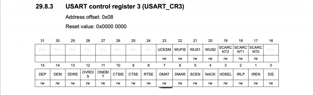
	/*Enable DMA TX for UART*/
	USART2->CR3|=USART_CR3_DMAT;
Finally enable the USART as following:
	/*Enable uart module*/
	USART2->CR1 |= USART_CR1_UE;
For DMA configuration, first enable clock access to DMA1:
RCC->AHBENR|=RCC_AHBENR_DMA1EN;
That all for the initializing.
2. DMA Send
Next configure the DMA each time the data to be send.
Fist thing first, we need to know which channel of the DMA has the connection with UART:
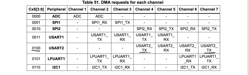
Since we can use channel4 or channel7, in this guide, channel 7 is selected.
Then declare a function that will take two arguments, pointer to the character array and the length:
void uart_transmit_dma(char *message, uint16_t len)
inside the function if the inprogress variable is 0 to proceed with the setup:
if(inprogress==0)
Within the if condition, disable the DMA1_Channel7 and wait until the DMA1_Channel7 is disabled:
			/*DMA1 Channel 7 is for USART_TX*/
			DMA1_Channel7->CCR &=~DMA_CCR_EN;

			while((DMA1_Channel7->CCR &DMA_CCR_EN));
For the configuration, we shall set the following:
- Memory Increment
- Read from Memory mode
- Transfer complete interrupt
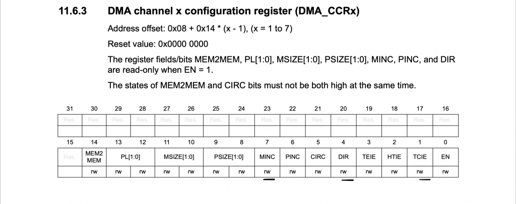
DMA1_Channel7->CCR|=DMA_CCR_MINC|DMA_CCR_DIR|DMA_CCR_TCIE;
Enable DMA interrupt in the NVIC (Channel4, 5, 6, 7 are shared all within the same handler):
NVIC_EnableIRQ(DMA1_Channel4_5_6_7_IRQn);
Set the peripheral destination to be USART2->TDR:
DMA1_Channel7->CPAR=(uint32_t)(&USART2->TDR);
Then we need to set C7S to value 4:
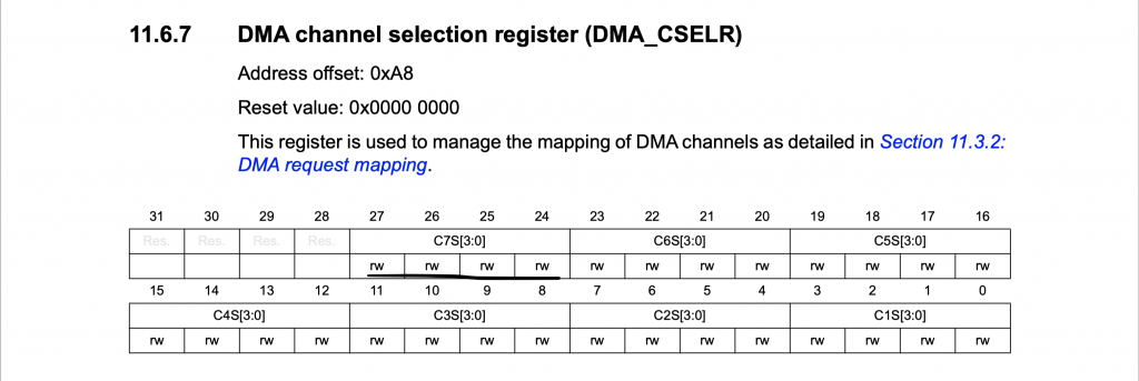
Since this register is not presented in the header file, we can create it as following:
#define DMA_CSELR (*(volatile unsigned int *)(0x400200a8))
Then set C7S to 4 as following:
DMA_CSELR|=(0x04<<24);
Then clear the transfer complete transfer of the DMA:
DMA1->IFCR|=DMA_IFCR_CTCIF7;
Set the memory address to be the message:
MA1_Channel7->CMAR=(uint32_t)message;
Set the length to be the length pass as argument:
DMA1_Channel7->CNDTR=(uint16_t)len;
Enable the Channel:
DMA1_Channel7->CCR|=DMA_CCR_EN;
Then set inprogress to 1:
			inprogress=1;
		}
Thats all for the if condition.
else condition is simple return :
else return;
For DMA interrupt handler:
void DMA1_Channel4_7_IRQHandler(void)
	{

		if(DMA1->ISR & DMA_ISR_TCIF7)
			{
				inprogress=0;
				DMA1->IFCR|=DMA_IFCR_CTCIF7;
			}

	}
In while loop:
while(1)
	{

		length=sprintf(data,"Counter value= %d\r\n",++counter);
		uart_transmit_dma(data,length);
		while(inprogress==1){;}

	}
3. Code:
Hence, the entire code as following:
#include "stm32l0xx.h"
#include "stdio.h"
#define SYS_FREQ		2097000
#define APB1_CLK		SYS_FREQ

#define UART_BAUDRATE	115200

volatile uint8_t finished=0, inprogress=0;


char data[40];
uint16_t length;


#define DMA_CSELR  (*(volatile unsigned int *)(0x400200a8))


static uint16_t compute_uart_bd(uint32_t PeriphClk, uint32_t BaudRate)
{
	return ((PeriphClk  +  (BaudRate/2U))/BaudRate);
}


void uart_transmit_dma(char *message, uint16_t len)
	{

		if(inprogress==0)
		{
			/*DMA1 Channel 7 is for USART_TX*/
			DMA1_Channel7->CCR &=~DMA_CCR_EN;

			while((DMA1_Channel7->CCR &DMA_CCR_EN));
			DMA1_Channel7->CCR|=DMA_CCR_MINC|DMA_CCR_DIR|DMA_CCR_TCIE;
			NVIC_EnableIRQ(DMA1_Channel4_5_6_7_IRQn);
			DMA1_Channel7->CPAR=(uint32_t)(&USART2->TDR);
			DMA_CSELR|=(0x04<<24);
			DMA1->IFCR|=DMA_IFCR_CTCIF7;
			DMA1_Channel7->CMAR=(uint32_t)message;
			DMA1_Channel7->CNDTR=(uint16_t)len;
			DMA1_Channel7->CCR|=DMA_CCR_EN;
			inprogress=1;
		}
		else return;
	}


int main(void)
{
	/*Enable clock access to GPIOA*/
	RCC->IOPENR |= RCC_IOPENR_GPIOAEN;
	GPIOA->MODER|=GPIO_MODER_MODE2_1;
	GPIOA->MODER&=~GPIO_MODER_MODE2_0;
	#define AF04 0x04
	GPIOA->AFR[0]|=(AF04<<8);


	RCC->APB1ENR |= RCC_APB1ENR_USART2EN;
	USART2->BRR=compute_uart_bd(APB1_CLK,UART_BAUDRATE);
	/*Configure transfer direction*/
	USART2->CR1 = USART_CR1_TE;
	/*Enable DMA TX for UART*/
	USART2->CR3|=USART_CR3_DMAT;
	/*Enable uart module*/
	USART2->CR1 |= USART_CR1_UE;

	/*Enable Clock access to DMA1*/
	RCC->AHBENR|=RCC_AHBENR_DMA1EN;
	uint16_t counter;
	while(1)
	{

		length=sprintf(data,"Counter value= %d\r\n",++counter);
		uart_transmit_dma(data,length);
		while(inprogress==1){;}

	}

}


void DMA1_Channel4_7_IRQHandler(void)
	{

		if(DMA1->ISR & DMA_ISR_TCIF7)
			{
				inprogress=0;
				DMA1->IFCR|=DMA_IFCR_CTCIF7;
			}

	}
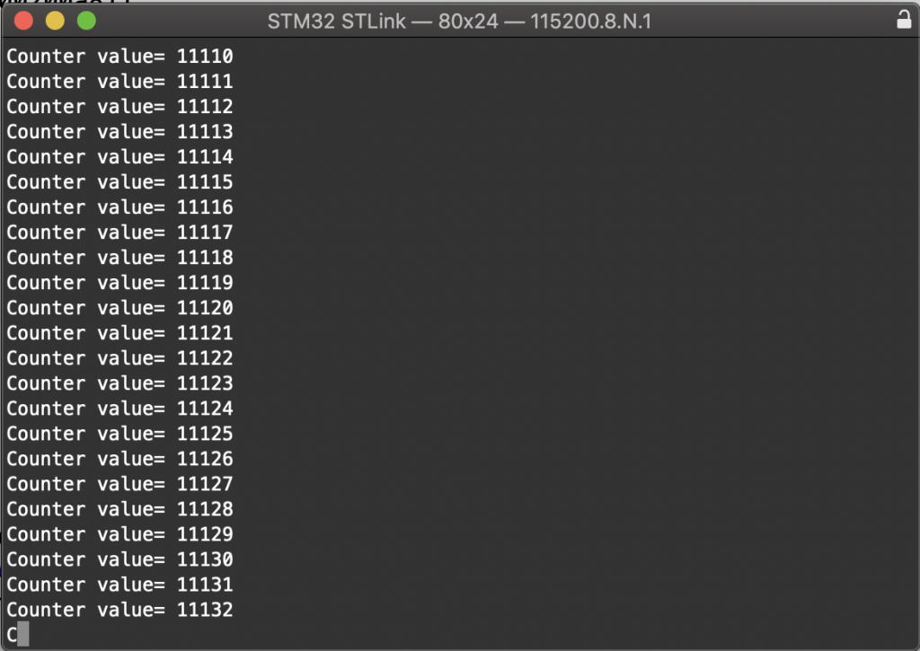
4. Results:
Upload the code to your MCU and open serial terminal and set the buadrate to 115200 and you should see the following:
Happy coding 🙂
Add Comment