In this guide, we shall see how to configure I2C peripheral in STM32F7 to read certain amount of data from memory location. In this guide, we shall use DS3231 RTC to read seconds, minutes and hours.
In this guide, we shall cover the following:
- What is I2C.
- Circuit Diagram.
- Configure I2C pins.
- Configure I2C peripheral.
- I2C Read function.
- Code.
- Result.
1. What is I2C:
With I2C, data is transferred in messages. Messages are broken up into frames of data. Each message has an address frame that contains the binary address of the slave, and one or more data frames that contain the data being transmitted. The message also includes start and stop conditions, read/write bits, and ACK/NACK bits between each data frame:
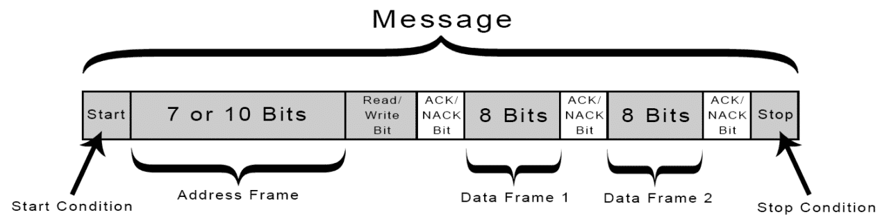
Start Condition: The SDA line switches from a high voltage level to a low voltage level before the SCL line switches from high to low.
Stop Condition: The SDA line switches from a low voltage level to a high voltage level after the SCL line switches from low to high.
Address Frame: A 7 or 10 bit sequence unique to each slave that identifies the slave when the master wants to talk to it.
Read/Write Bit: A single bit specifying whether the master is sending data to the slave (low voltage level) or requesting data from it (high voltage level).
ACK/NACK Bit: Each frame in a message is followed by an acknowledge/no-acknowledge bit. If an address frame or data frame was successfully received, an ACK bit is returned to the sender from the receiving device.
For more information and detailed explanations refer to this NXP documentation (here).
2. Circuit Diagram:
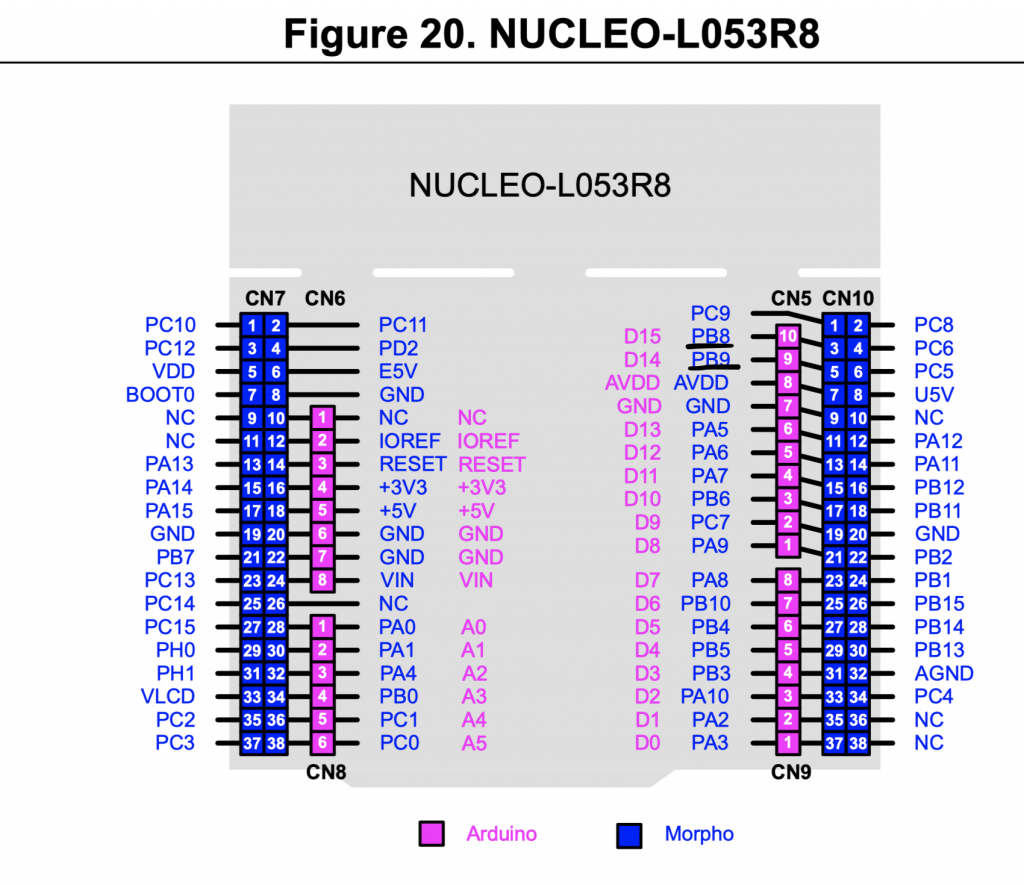
Since here we are using STM32L053-Nucleo64, there is SDA and SCL pins in arduino connectors that allow us to connect I2C devices such as OLED display MPU9250 etc.
These pins are PB8 and PB9
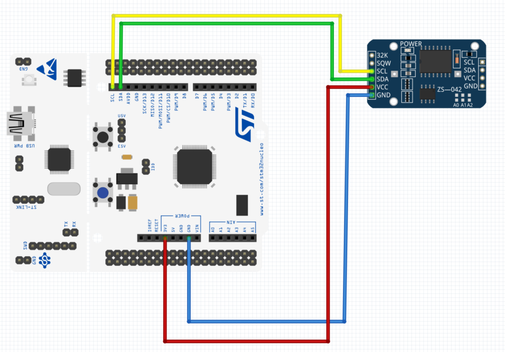
| STM32L053-Nucleo64 | DS3231 module |
| 5V | Vcc |
| GND | GND |
| D15 (PB8) | SCL |
| D14 (PB9) | SDA |
3. Configure I2C pins:
From the circuit diagram, the required pins are PB8 and PB9.
Now we need to configure the pins.
We need first to enable clock access to GPIOB:
RCC->IOPENR|=RCC_IOPENR_GPIOBEN;
Then we need to get the AF number for PB8 and PB9 for I2C1. From the datasheet, we can find that the AF4 is for I2C1:
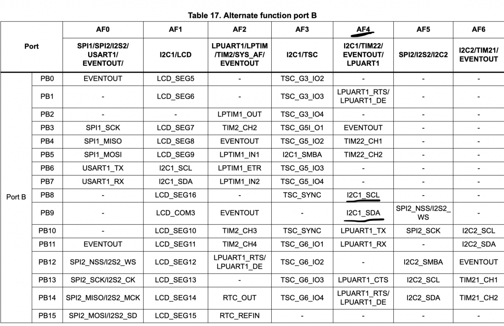
Hence, we can create a symbolic name:
const uint8_t AF04 =0x04;
Then set PB8 and PB9 to alternate function, set the output type to open drain, the speed to maximum and alternate function type.
	GPIOB->MODER&=~(GPIO_MODER_MODE8|GPIO_MODER_MODE9);
	GPIOB->MODER|=GPIO_MODER_MODE8_1|GPIO_MODER_MODE9_1;
	GPIOB->OTYPER|=GPIO_OTYPER_OT_8|GPIO_OTYPER_OT_9;
	GPIOB->OSPEEDR|=GPIO_OSPEEDER_OSPEED8_0|GPIO_OSPEEDER_OSPEED8_1|GPIO_OSPEEDER_OSPEED9_0|GPIO_OSPEEDER_OSPEED9_1;
	GPIOB->AFR[1]|=(AF04<<0)|(AF04<<4);
4. Configure I2C:
Then enabled clock access to I2C1.
From the block diagram in the datasheet of STM32L053, we can see that I2C is connected to APB1 bus:
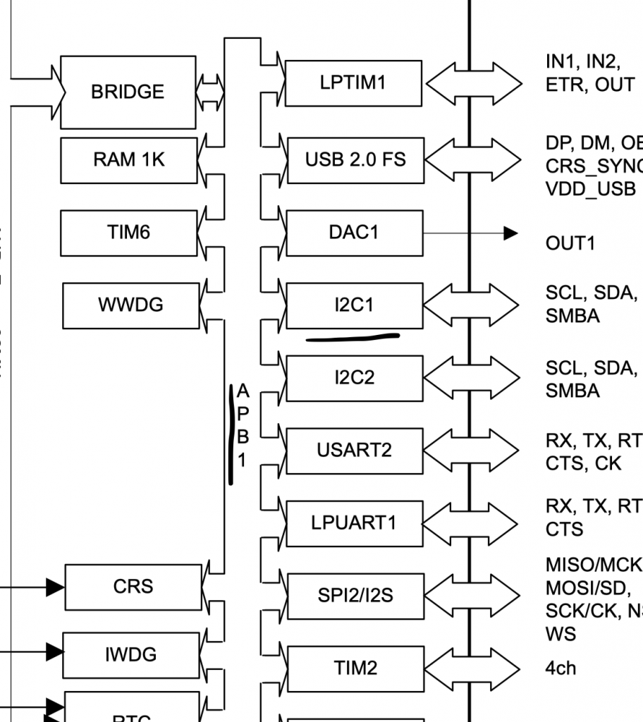
Hence, we can enable clock access to I2C1 as following:
RCC->APB1ENR|=RCC_APB1ENR_I2C1EN;
Then we software reset the I2C:
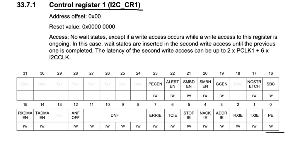
I2C1->CR1 &=~I2C_CR1_PE;
Set the timing register (taken from STM32CubeMX):
#define timing 0x00708
I2C1->TIMINGR=timing;
Then enable I2C:
I2C1->CR1 |=I2C_CR1_PE;
5. I2C read function:
For reading, we create function that takes 4 arguments:
- Slave address.
- Memory address.
- Pointer to hold the data to be read.
- Number of bytes to be read.
void i2_read(uint8_t slav_add, uint8_t memadd, uint8_t *data, uint8_t length )
{
/*Enable I2C*/
I2C1->CR1 |=I2C_CR1_PE;
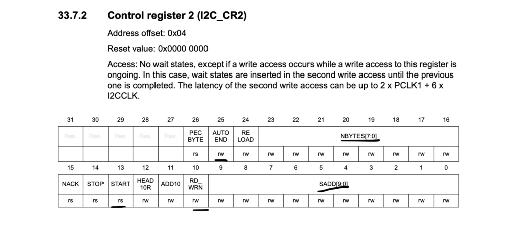
/*Set slave address*/
I2C1->CR2=(slav_add<<1);
/*7-bit addressing*/
I2C1->CR2&=~I2C_CR2_ADD10;
/*Set number to transfer to 1 for write operation*/
I2C1->CR2|=(1<<I2C_CR2_NBYTES_Pos);
/*Set the mode to write mode*/
I2C1->CR2&=~I2C_CR2_RD_WRN;
/*Software end*/
I2C1->CR2&=~I2C_CR2_AUTOEND;
/*Generate start*/
I2C1->CR2|=I2C_CR2_START;
/*Wait until transfer is completed*/
while(!(I2C1->ISR & I2C_ISR_TC)){
/*Check if TX buffer is empty*/
if(I2C1->ISR & I2C_ISR_TXE)
{
/*send memory address*/
I2C1->TXDR = (memadd);
}
}
/*Reset I2C*/
I2C1->CR1 &=~I2C_CR1_PE;
I2C1->CR1 |=I2C_CR1_PE;
/*Set slave address*/
I2C1->CR2=(slav_add<<1);
/*Set mode to read operation*/
I2C1->CR2|=I2C_CR2_RD_WRN;
/*Set length to the required length*/
I2C1->CR2|=((length)<<I2C_CR2_NBYTES_Pos);
/*aut generate stop after transfer completed*/
I2C1->CR2|=I2C_CR2_AUTOEND;
/*Generate start*/
I2C1->CR2|=I2C_CR2_START;
/*wait until stop is generated*/
while(!(I2C1->ISR & I2C_ISR_STOPF))
{
/*If RX buffer is empty*/
if(I2C1->ISR &(I2C_ISR_RXNE))
{
/*read the data and increment the pointer*/
*data++=I2C1->RXDR;
}
}
/*disable the peripheral*/
I2C1->CR1 &=~I2C_CR1_PE;
}Hence, the source code as following:
#include "i2c.h"

const uint8_t AF04 =0x04;

void i2c_init(uint32_t timing)
{
	RCC->IOPENR|=RCC_IOPENR_GPIOBEN;
	GPIOB->MODER&=~(GPIO_MODER_MODE8|GPIO_MODER_MODE9);
	GPIOB->MODER|=GPIO_MODER_MODE8_1|GPIO_MODER_MODE9_1;
	GPIOB->OTYPER|=GPIO_OTYPER_OT_8|GPIO_OTYPER_OT_9;
	GPIOB->OSPEEDR|=GPIO_OSPEEDER_OSPEED8_0|GPIO_OSPEEDER_OSPEED8_1|GPIO_OSPEEDER_OSPEED9_0|GPIO_OSPEEDER_OSPEED9_1;
	GPIOB->AFR[1]|=(AF04<<0)|(AF04<<4);

	RCC->APB1ENR|=RCC_APB1ENR_I2C1EN;
	I2C1->CR1 &=~I2C_CR1_PE;
	I2C1->TIMINGR=timing;
	I2C1->CR1 |=I2C_CR1_PE;


}

void i2_read(uint8_t slav_add, uint8_t memadd, uint8_t *data, uint8_t length )
	{
	(slav_add=slav_add<<1);
	/*Enable I2C*/
	I2C1->CR1 |=I2C_CR1_PE;
	/*Set slave address*/
	I2C1->CR2=(slav_add<<I2C_CR2_SADD_Pos);
	/*7-bit addressing*/
	I2C1->CR2&=~I2C_CR2_ADD10;
	/*Set number to transfer to 1 for write operation*/
	I2C1->CR2|=(1<<I2C_CR2_NBYTES_Pos);
	/*Set the mode to write mode*/
	I2C1->CR2&=~I2C_CR2_RD_WRN;
	/*Software end*/
	I2C1->CR2&=~I2C_CR2_AUTOEND;
	/*Generate start*/
	I2C1->CR2|=I2C_CR2_START;
	/*Wait until transfer is completed*/
	while(!(I2C1->ISR & I2C_ISR_TC)){
		/*Check if TX buffer is empty*/
		if(I2C1->ISR & I2C_ISR_TXE)
		{
			/*send memory address*/
			I2C1->TXDR = (memadd);
		}
	}
	/*Reset I2C*/
	I2C1->CR1 &=~I2C_CR1_PE;
	I2C1->CR1 |=I2C_CR1_PE;
	/*Set slave address*/
	I2C1->CR2=(slav_add<<I2C_CR2_SADD_Pos);
	/*Set mode to read operation*/
	I2C1->CR2|=I2C_CR2_RD_WRN;
	/*Set length to the required length*/
	I2C1->CR2|=((length)<<I2C_CR2_NBYTES_Pos);
	/*aut generate stop after transfer completed*/
	I2C1->CR2|=I2C_CR2_AUTOEND;
	/*Generate start*/
	I2C1->CR2|=I2C_CR2_START;
	/*wait until stop is generated*/
	while(!(I2C1->ISR & I2C_ISR_STOPF))
			{
				/*If RX buffer is empty*/
			  if(I2C1->ISR &(I2C_ISR_RXNE))
			  	  {
				  /*read the data and increment the pointer*/
				  *data++=I2C1->RXDR;
				 }
			}
	/*disable the peripheral*/
	I2C1->CR1 &=~I2C_CR1_PE;
	}
The header file as following:
#ifndef I2C_H_
#define I2C_H_

#include "stdint.h"
#include "stm32l0xx.h"

void i2c_init(uint32_t timing);
void i2_read(uint8_t slav_add, uint8_t memadd, uint8_t *data, uint8_t length );
void i2c_write(uint8_t slav_add, uint8_t *data, uint8_t length);
void i2c_write_memory(uint8_t slav_add, uint8_t memadd, uint8_t *data, uint8_t length);
#endif /* I2C_H_ */
In the main function, we can call the initializing function and read function:
#include "i2c.h"
#include "uart.h"
#include "stdio.h"
#include "stdlib.h"
#define slave_add (0x68)


uint8_t data[3],data_send[3];

int bcd_to_decimal(unsigned char x) {
    return x - 6 * (x >> 4);
}

int main()
	{
	uart_init();
	i2c_init(0x00708);
	while(1)
		{
		i2_read(slave_add,0x00,data,3);
		for (volatile int i=0;i<3;i++)
			{
			data[i]=bcd_to_decimal(data[i]);

			}
		printf("rtc data %d %d %d\r\n",data[0],data[1],data[2]);
		for (volatile int i=0;i<100000;i++);
		}

	}
For the serial function from here and for retargeting printf from here (replace ITM_SendChar with uart_write).
6. Results:
If you run the code and open terminal application and set baudrate to 9600, you should get the following:
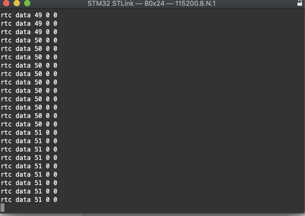
From left to right:
- Seconds.
- Minutes.
- Hours.
Happy coding 🙂
2 Comments
I am working with scd4x sensor. This code is note working with it. Can you guide me how to adjust the code accordingly.
Start from the datasheet, check the registers etc.
Add Comment