
In this guide, we shall see how to receive data using UART in LIN configuration.
In this guide, we shall cover the following:
- STM32CubeMX setup.
- Firmware modification.
- Hardware connection.
- Results.
1. STM32CubeMX Setup:
We shall pickup from the previous guide from here.
Open LIN_Bus project from STM32CubeMX.
Once the project has been opened, enable USART6 in LIN mode as follows:
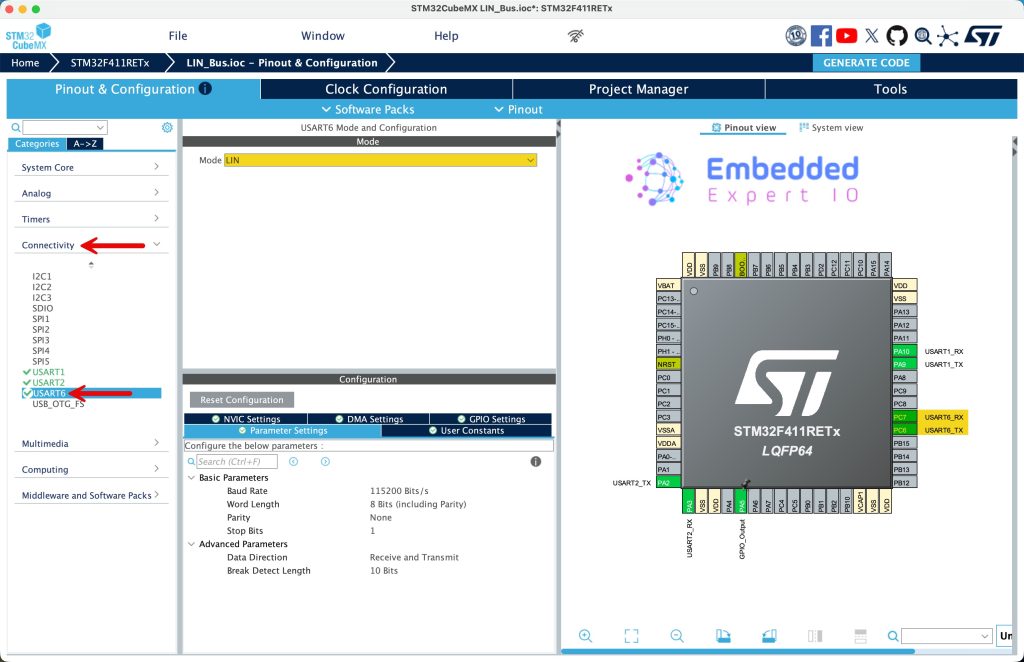
This will enable PC6 and PC7 for USART6_TX and USART_RX respectively.
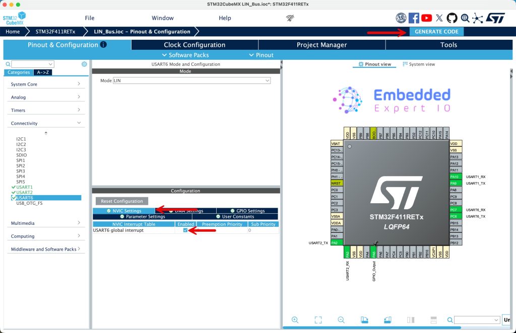
Next, from NVIC Settings, enable global interrupt for USART6, once it has been enabled, click on generate code as follows:
2. Firmware Modification:
Once the project has been generated, open the project in STM32CubeIDE.
Open LIN.h header and declare the checksum function as follows:
uint8_t checksum_Calc (uint8_t PID, uint8_t *data, int size);
In the source LIN.c file, modify the following function:
static uint8_t checksum_Calc (uint8_t PID, uint8_t *data, int size)
To become:
uint8_t checksum_Calc (uint8_t PID, uint8_t *data, int size)
This will allow us to access the function from another source files.
Next, in main.c source file, in user code PV section, declare the following:
uint8_t data_rx[20];

uint8_t LIN_Rx_Data[8];
- data_rx is the buffer to receive LIN frame data.
- LIN_Rx_Data is the 8 received bytes.
Also, declare the following:
uint32_t previous_ticks=0;

uint8_t numDataBytes;

volatile uint8_t isDataValid;
- previous_ticks which store the ticks.
- numDataBytes is the amount of received data.
- isDataValid indicates the success of reception of the data.
In user code begin 0:
void HAL_UARTEx_RxEventCallback(UART_HandleTypeDef *huart, uint16_t Size)
{
	 numDataBytes = Size - 4;
	uint8_t checksum = checksum_Calc(data_rx[2], data_rx+3, numDataBytes);
	ID = data_rx[2]&0x3F;
	if (checksum != data_rx[Size-1])
	{
		isDataValid = 0;

	}
	else
	{
		isDataValid = 1;
	}
	HAL_UARTEx_ReceiveToIdle_IT(&huart6, data_rx, 20);
}
This function is a UART receive callback used with the STM32F4 HAL driver when Receive-to-IDLE interrupt modeis enabled.
The callback HAL_UARTEx_RxEventCallback() is automatically called by the HAL when the UART detects an IDLE line condition, meaning that a complete frame has been received or the sender has stopped transmitting.
The parameter Size represents the number of bytes actually received before the IDLE condition occurred.
The line:
numDataBytes = Size - 4;
indicates that the communication protocol reserves 4 bytes for non-payload data, such as header, ID, control fields, and checksum. The remaining bytes are considered payload data.
Next, a checksum is calculated:
checksum_Calc(data_rx[2], data_rx + 3, numDataBytes);
Here:
data_rx[2]is likely a command or device ID field.data_rx + 3points to the beginning of the payload.numDataBytesspecifies how many payload bytes are included in the checksum calculation.
The device ID is then extracted using:
ID = data_rx[2] & 0x3F;
The bitmask 0x3F keeps only the lower 6 bits of the ID field, discarding any control or flag bits stored in the upper bits.
The received checksum (last byte of the frame) is compared with the calculated checksum:
data_rx[Size - 1]
If the two values do not match, the received data is marked as invalid. Otherwise, it is marked as valid.
Finally, UART reception is restarted:
HAL_UARTEx_ReceiveToIdle_IT(&huart6, data_rx, 20);
This re-arms USART6 to receive the next frame using IDLE line detection, with a maximum buffer size of 20 bytes.
In summary, this callback:
- Handles variable-length UART frames
- Extracts payload and ID information
- Verifies data integrity using a checksum
- Automatically restarts reception for continuous communication
In user code begin 2 in main function, start the USART6 to receive data until IDLE detected as follows:
HAL_UARTEx_ReceiveToIdle_IT(&huart6, data_rx, 20);
In user code begin 3 in while 1 loop:
	  if(HAL_GetTick()-previous_ticks>100)
	  {
		  for (int i=0;i<8;i++)
		  {
			  data[i]=random()%255;
		  }
		  ID=random()%255;

		  LIN_State=LinTransmit(ID,data);

		  if(LIN_State==Timeout)
		  {
			  uint16_t len=sprintf(uart_data,"Timeout communication\r\n");
			  HAL_UART_Transmit(&huart2, uart_data, len, 1000);

		  }

		  if(LIN_State==InvalideID)
		  {
			  uint16_t len=sprintf(uart_data,"Invalid ID\r\n");
			  HAL_UART_Transmit(&huart2, uart_data, len, 1000);
		  }

		  previous_ticks=HAL_GetTick();

	  }

	  if(isDataValid==1)
	  {
		  uint16_t len=sprintf(uart_data,"LIN Data Received\r\n");
		  HAL_UART_Transmit(&huart2, uart_data, len, 1000);

		  for (int i=0; i<numDataBytes; i++)
		  {
			  LIN_Rx_Data[i] = data_rx[i+3];
		  }
		  isDataValid = 0;
	  }
Save the project, build it and run it in debugging mode on your STM32F4 board.

3. Hardware Setup:
The connection is as simple as connecting PC7 to PA9 using jumper wire as following:
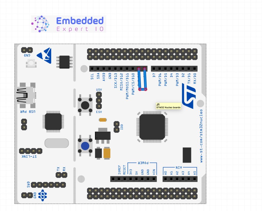
Simply, connect a wire from D8 to D9 of the arduino header.
4. Results:
In live expression of the debug session, add data and LIN_Rx_Data to live expression.
Run the project, you should see from time to time there is incoming data as follows:
Using serial terminal application, you should see the following:
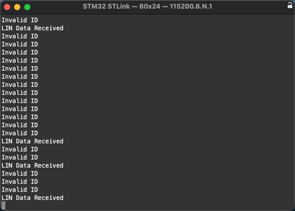
We have successfully received LIN also, transmitted data and prevent incorrect ID to be send.
Happy coding 😉
Add Comment