
In previous two guides, we discussed how to use timer to generate delay (here).
In this guide, we shall look how to configure TIM2 to generate an interrupt every second and toggle an led every second.
In this guide, we will cover the following
- What is an interrupt
- Configure TIM2 to generate Interrupt
- Code
- Demo
1. What is an interrupt:
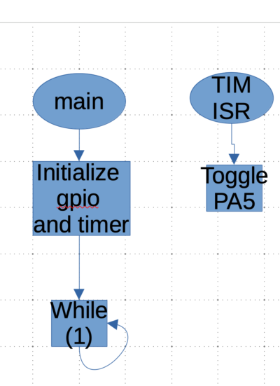
Interrupt is a process to notify the cpu that there is a request and it should be handled as soon as possible See figure below.
The CPU will find the current instruction in the main loop (which is empty in our case) and jump to ISR function to toggle PA5 and jump back to main loop.
For more information, please refer to this guide (here)
2. Configure TIM2 to generate interrupt:
We starting by getting to know which timer to use, in this case , we will use TIMER2.
Hence, we need to know which bus is connected to. From the diagram, TIMER2 is connected to APB1 bus.
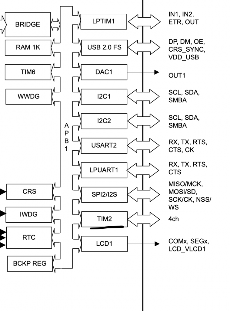
Hence, we can enable clock access to timer2 as following:
- Enabled clock access to TIM2
- Set prescaller to 2097 since STM32l053 is running at 2.09MHz.
- Set ARR to 999.
	RCC->APB1ENR|=RCC_APB1ENR_TIM2EN;
	TIM2->PSC=2097-1;
	TIM2->ARR=1000-1;
Then enable Update interrupt in DIER register:
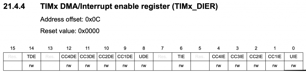
TIM2->DIER|=TIM_DIER_UIE;
Enable the interrupt in the NVIC as following:
NVIC_EnableIRQ(TIM2_IRQn);
Finally, start the timer:
TIM2->CR1|=TIM_CR1_CEN;
For the interrupt handler:
void TIM2_IRQHandler(void)
	{
	if(1==(TIM_SR_UIF&TIM2->SR)) /*Check interrupt update flag */
		{
		GPIOA->ODR^=GPIO_ODR_OD5; /*Toggle the LED*/
		TIM2->SR&=~TIM_SR_UIF; /*Clear update interrupt flag*/
		}

	}
3. Code:
You may download the code from here:
4. Demo:
Happy coding 🙂
Add Comment