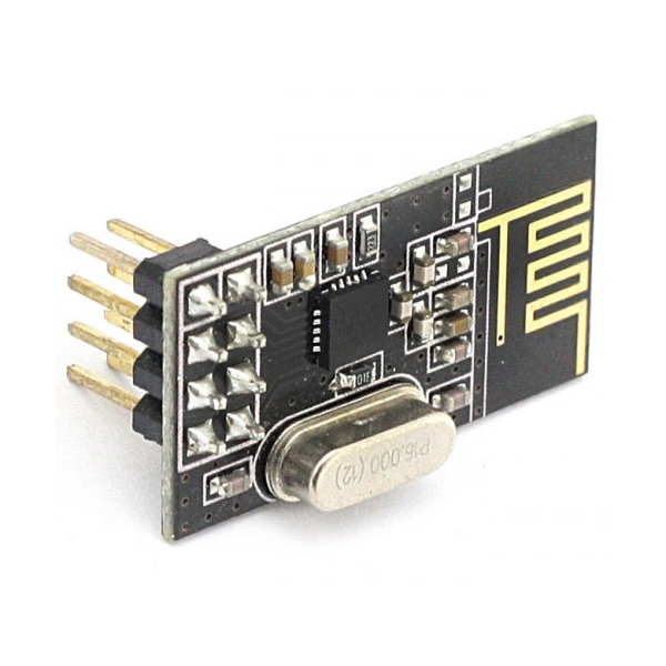
In the previous guide(here), we saw to configure the module in Transmission mode. In this guide, we shall see how to configure the module to receive the data from the another module.
In this guide, we will cover the following:
- Configure the module in RX.
- Check if data is available.
- Read the data from the buffer.
- Main code.
- Source code.
- Demo.
1. Configure the module in RX:
We start of by defining the function which take two arguments, point to address array and the channel number.
void NRF24_RxMode (uint8_t *Address, uint8_t channel)
Then we disable the chip as following:
CE_Disable();
Reset the module:
nrf24_reset (STATUS);
Write the channel number to the module:
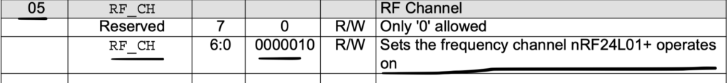
nrf24_WriteReg (RF_CH, channel); // select the channel
Now we select pipe line 2:
In order to select pipeline2 , we need only to set the respective bit:
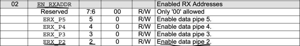
Hence, we shall read the register, set bit2 and write the value back to the register as following:
// select data pipe 2
	uint8_t en_rxaddr = nrf24_ReadReg(EN_RXADDR);
	en_rxaddr = en_rxaddr | (1<<2);
	nrf24_WriteReg (EN_RXADDR, en_rxaddr);
Now, we insert the address to pipeline1 :
nrf24_WriteRegMulti(RX_ADDR_P1, Address, 5); // Write the Pipe1 address
Write the address to pipeline2
nrf24_WriteReg(RX_ADDR_P2, 0xEE); // Write the Pipe2 LSB address
Set the received payload of 32-bit for pipeline2
nrf24_WriteReg (RX_PW_P2, 32); // 32 bit payload size for pipe 2
Now, we power up the module as following:
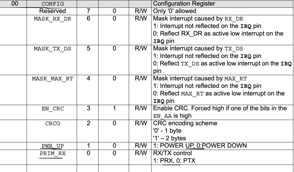
	// power up the device in Rx mode
	uint8_t config = nrf24_ReadReg(CONFIG);
	config = config | (1<<1) | (1<<0);
	nrf24_WriteReg (CONFIG, config);
Finally, enable the chip:
	// Enable the chip after configuring the device
	CE_Enable();
2. Check if data is available:
We declare the function that will take single argument which is the pipeline. The function shall return 1 if data is available or 0 if not:
uint8_t isDataAvailable (int pipenum)
We can check the FIFO as followingL
	uint8_t status = nrf24_ReadReg(STATUS);

	if ((status&(1<<6))&&(status&(pipenum<<1)))
	{

		nrf24_WriteReg(STATUS, (1<<6));

		return 1;
	}

	return 0;
3. Read the data:
We declare the function which takes a pointer to array to hold the data:
void NRF24_Receive (uint8_t *data)
Then we can read the FIFO as following:
	uint8_t cmdtosend = 0;

	// select the device
	CS_Select();

	// payload command
	cmdtosend = R_RX_PAYLOAD;
	spi1_transmit( &cmdtosend, 1);

	// Receive the payload
	spi1_receive(data, 32);

	// Unselect the device
	CS_UnSelect();

	delay(1);

	cmdtosend = FLUSH_RX;
	nrfsendCmd(cmdtosend);
4. Main code:
We shall use SWO to print the received string (from here)
#include "delay.h"
#include "led.h"
#include "nRF.h"
#include "stdio.h"
#include "stm32f4xx.h"
/*RX section*/
uint8_t RxAddress[] = {0x00,0xDD,0xCC,0xBB,0xAA};
uint8_t RxData[32];

void print(uint8_t *data, uint32_t len)
	{
	for (int i=0;i<len;i++)
		{
		ITM_SendChar(data[i]);
		}

	}

int main()
	{
	led_init();
	delay_init(16000000);
	NRF24_Init();
	NRF24_RxMode(RxAddress, 10);
	//NRF24_ReadAll(data);

	while(1)
		{

		if (isDataAvailable(2) == 1)
			  {
				  NRF24_Receive(RxData);
				  toggle_led();
				  print(RxData,32);
			  }

		}

	}
5. Source Code:
You may download the source code from here:
6. Demo:
Happy coding 🙂
1 Comment
Hi Husamuldeen. Thank you very much for all the tutorials! 🙂
Add Comment