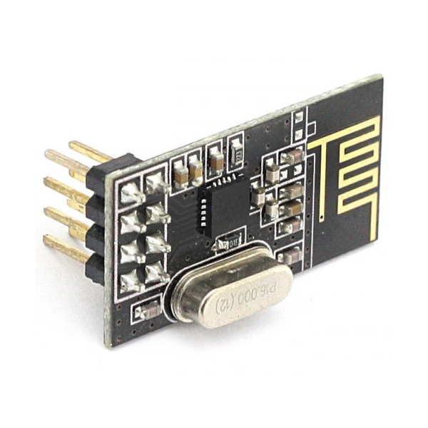
In the previous guide(here), we take a look at NRF24L01 and configured the required peripheral and initialized the module. In this guide, we shall send data using this module and how to received it in part3.
In this guide, we will cover the following:
- Setting the module to TX.
- Send data function.
- Main code.
- Demo.
1. Setting the module to TX mode:
First we create a function that takes two arguments, first argument is the address as a pointer and channel number.
void NRF24_TxMode (uint8_t *Address, uint8_t channel)
In order to set the module in TX, we need first to set the channel:
First we disable the module as following:
CE_Disable();
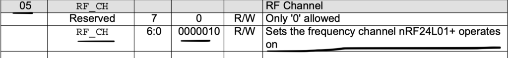
Then we configure the channel using send command:
nrf24_WriteReg (RF_CH, channel); // select the channel
Then we write the address using write to multiple register as following:
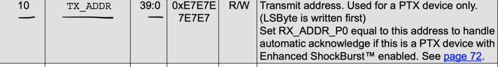
nrf24_WriteRegMulti(TX_ADDR, Address, 5); // Write the TX address
Then we power up the module in configuration register:
Since we need to configure single bit, we need to read the register first, modify the required bit and send the new configuration back to module.
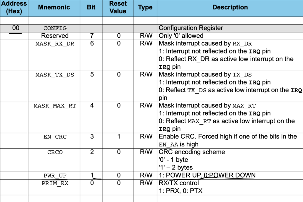
uint8_t config = nrf24_ReadReg(CONFIG);
	config = config | (1<<1);   // write 1 in the PWR_UP bit
//	config = config & (0xF2);    // write 0 in the PRIM_RX, and 1 in the PWR_UP, and all other bits are masked
	nrf24_WriteReg (CONFIG, config);
Finally we enable the chip:
	// Enable the chip after configuring the device
	CE_Enable();
2. Sending data function:
Since the module is configured to send 32-byte of data, we need first to send the payload telling the module that the following is data to be sent.
First we declare the TX function which takes a pointer to data array:
uint8_t NRF24_Transmit (uint8_t *data)
The function shall return 0 if failed and 1 if success.
Then we declare local variable as following:
uint8_t cmdtosend = 0;
Then select the device by setting CS to low:
CS_Select();
Then we send the payload as following:
// payload command
cmdtosend = W_TX_PAYLOAD;
spi1_transmit( &cmdtosend, 1);
Then transfer the full 32byte of data
// send the payload
spi1_transmit(data, 32);
Then deselect the chip and wait for 1ms
	// Unselect the device
	CS_UnSelect();
	delay(1);
Then we need to check the FIFO if the data has been transferred or not as following:
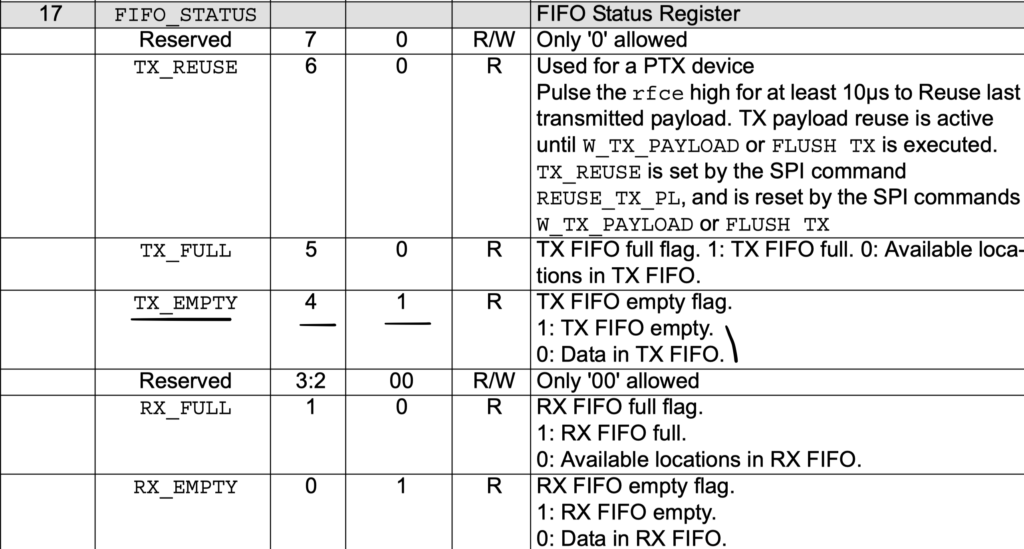
 fifostatus = nrf24_ReadReg(FIFO_STATUS);

	// check the fourth bit of FIFO_STATUS to know if the TX fifo is empty
	if ((fifostatus&(1<<4)) && (!(fifostatus&(1<<3))))
	{
		cmdtosend = FLUSH_TX;
		nrfsendCmd(cmdtosend);

		// reset FIFO_STATUS
		nrf24_reset (FIFO_STATUS);

		return 1;
	}

	return 0;
3. Main Code:
#include "delay.h"
#include "led.h"
#include "nRF.h"

/*TX Section*/
uint8_t TxAddress[] = {0xEE,0xDD,0xCC,0xBB,0xAA};
uint8_t TxData[] = "Hello World\n";
int main()
	{
	led_init();
	delay_init(16000000);
	NRF24_Init();
	NRF24_TxMode(TxAddress, 10);

	while(1)
		{

			  if (NRF24_Transmit(TxData) == 1)
			  {
				  toggle_led();
			  }

			  delay(1000);

		}

	}
4. Demo:
As you can see, the LED is blinking which indicates that the data is being send successfully.
In next part we shall receive the sent data over uart.
Happy coding
5 Comments
Thanks for these great contents, and I m waiting for recieving data with nrf24l01. Thanks in advance
Hello, I have a question, why do you check 4th and 3rd bits in FIFOSTATUS . Shouldnot we check 4th and 5th? in order to know if there is data in fıfotx and if it is full?
In this case, we are checking if the transmission is done over pipeline 0 which is the pipeline used in this article.
Hi, quick question. Why do you check only fifo? There is interrupt bit TX_DS in STATUS register, which indicates that data transmitted.
Since we are using polling mode, hence we are checking for the FIFO.
Feel free to implement interrupt driven driver.
Add Comment