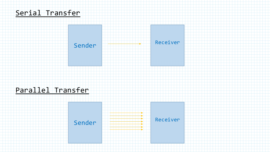
Computers transfer data in two ways: parallel and serial. In parallel data transfers, often eight or more lines (wire conductors) are used to transfer data to another device. In serial communication, the data is sent one bit at a time. In the past, parallel data transfer was preferred for short distance because it may transfer multiple bits at the same time and provides higher throughput. As technology advances, the data rate of serial communication sometimes exceed parallel communication while parallel communication still retains the disadvantages of the size and cost of cable and connector, the crosstalk between the data lines and the difficulty of synchronizing the arrival time of data lines at longer distance. UART is one of the most common serial communication protocols.
UART Protocol Summary
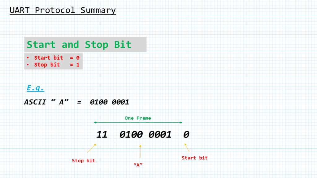
The data coming in at the receiving end of the data line in a serial data transfer is all 0s and 1s; it is difficult to make sense of the data unless the sender and receiver agree on a set of rules, a protocol, on how the data is packed, how many bits constitute a character, and when the data begins and ends. Asynchronous serial data communication like the uart is widely used for character-oriented transmissions. In the asynchronous method, each character, such as ASCII characters, is packed between start and stop bits. This is called framing. The start bit is always one bit but the stop bit can be one or two bits. The start bit is always a 0 (low) and the stop bit( s) is 1 (high). For instance, over here we are sending the ASCII character “A”, which has a binary number binary 0100 0001
As we can see the data is framed between the start bit and 2 stop bits. The rightmost bit or the LSB is sent first. LSB stand for least significant bit.
In asynchronous serial communications, peripheral chips can be programmed for data that is 5, 6, 7, or 8 bits wide. While in older systems ASCII characters were 7-bit, the modern systems usually send non-ASCII 8-bit data as well
Parity
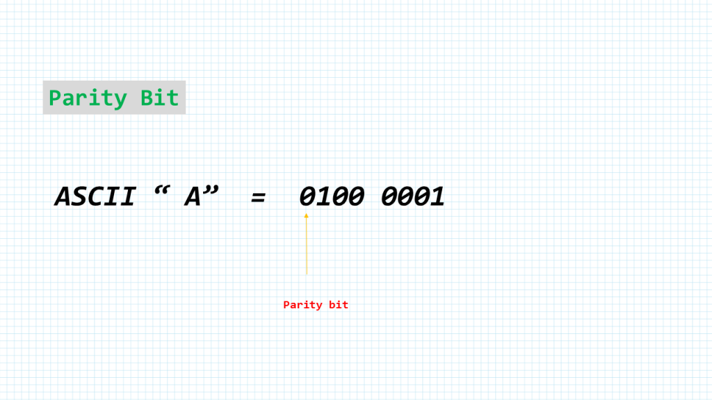
In some systems in order to maintain data integrity, the parity bit of the character byte is included in the data frame. This means that for each character (7- or 8-bit, depending on the system) we have a single parity bit in addition to start and stop bits. The parity bit may be odd or even. In the case of an odd-parity the number of data bits, including the parity bit, has an odd number of 1s. Similarly, in an even-parity the total number of bits, including the parity bit, is even.
For example, the ASCII character “A”, binary 0100 0001, has 0 for the even-parity bit. UART chips allow programming of the parity bit for odd-, even-, and even no-parity options.
Data transfer rate
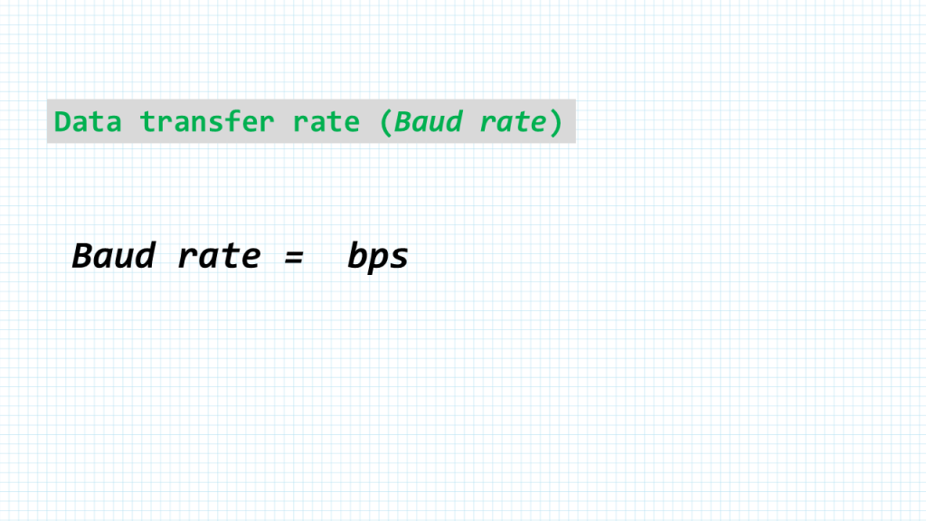
The rate of data transfer in serial data communication is stated in bps (or bits per second). Another widely used terminology for bps is Baud rate. However, the baud and bps rates are not necessarily equal. This is due to the fact that baud rate is defined as number of signal changes per second.
In modems, it is possible for each signal to transfer multiple bits of data. But when we are talking about wired communications like the uart the baud rate and bps are the same.
STM32F411-NUCLEO UART DRIVER
#include "stm32F4xx.h"

void USART2_init(void);
char USART2_read(void);
void LED_blink(int value);
void delayMs(int);

int main (void) {
    char c;

    RCC->AHB1ENR |=  1;             /* enable GPIOA clock */
    GPIOA->MODER &= ~0x00000C00;    /* clear pin mode */
    GPIOA->MODER |=  0x00000400;    /* set pin to output mode */

    USART2_init();                  /* initialize USART2 */

    while(1) {                      /* Loop forever */
        c = USART2_read();          /* wait for a character received */
        LED_blink(c);               /* blink the LED */
    }
}


void USART2_init (void) {
    RCC->AHB1ENR |= 1;          /* Enable GPIOA clock */
    RCC->APB1ENR |= 0x20000;    /* Enable USART2 clock */

    /* Configure PA3 for USART2 RX */
    GPIOA->AFR[0] &= ~0xF000;
    GPIOA->AFR[0] |=  0x7000;   /* alt7 for USART2 */
    GPIOA->MODER  &= ~0x00C0;
    GPIOA->MODER  |=  0x0080;   /* enable alternate function for PA3 */

    USART2->BRR = 0x008B;       /* 115200 baud @ 16 MHz */
    USART2->CR1 = 0x0004;       /* enable Rx, 8-bit data */
    USART2->CR2 = 0x0000;       /* 1 stop bit */
    USART2->CR3 = 0x0000;       /* no flow control */
    USART2->CR1 |= 0x2000;      /* enable USART2 */
}

/* Read a character from USART2 */
char USART2_read(void) {
    while (!(USART2->SR & 0x0020)) {}   // wait until char arrives
    return USART2->DR;
}

/* turn on or off the LEDs according to the value */
void LED_blink(int value) {
    value %= 16;                    /* cap the max count at 15 */

    for (; value > 0; value--) {
        GPIOA->BSRR = 0x00000020;   /* turn on LED */
        delayMs(200);
        GPIOA->BSRR = 0x00200000;   /* turn off LED */
        delayMs(200);
    }
    delayMs(800);
}

void delayMs(int n) {
    int i;
    for (; n > 0; n--)
        for (i = 0; i < 3000; i++) ;
}
Add Comment