In this guide, we shall investigate the GPS and how it works and use NEO-6M GPS module to locate our location in any part of world.
In this guide, we shall cover the following:
- What is GPS
- NEO-6M GPS sensor
- Connection with STM32
- Code
- Result
1. What is GPS:
Humans have looked to the skies to find their way since ancient times. Ancient sailors used the constellations in the night sky to figure out where they were and where they were going.
Today, all we need is a simple hand-held GPS (short for Global Positioning System) receiver to figure out exactly where we are anywhere in the world. But we still need objects high in the sky to figure out where we are and how we get to other places.
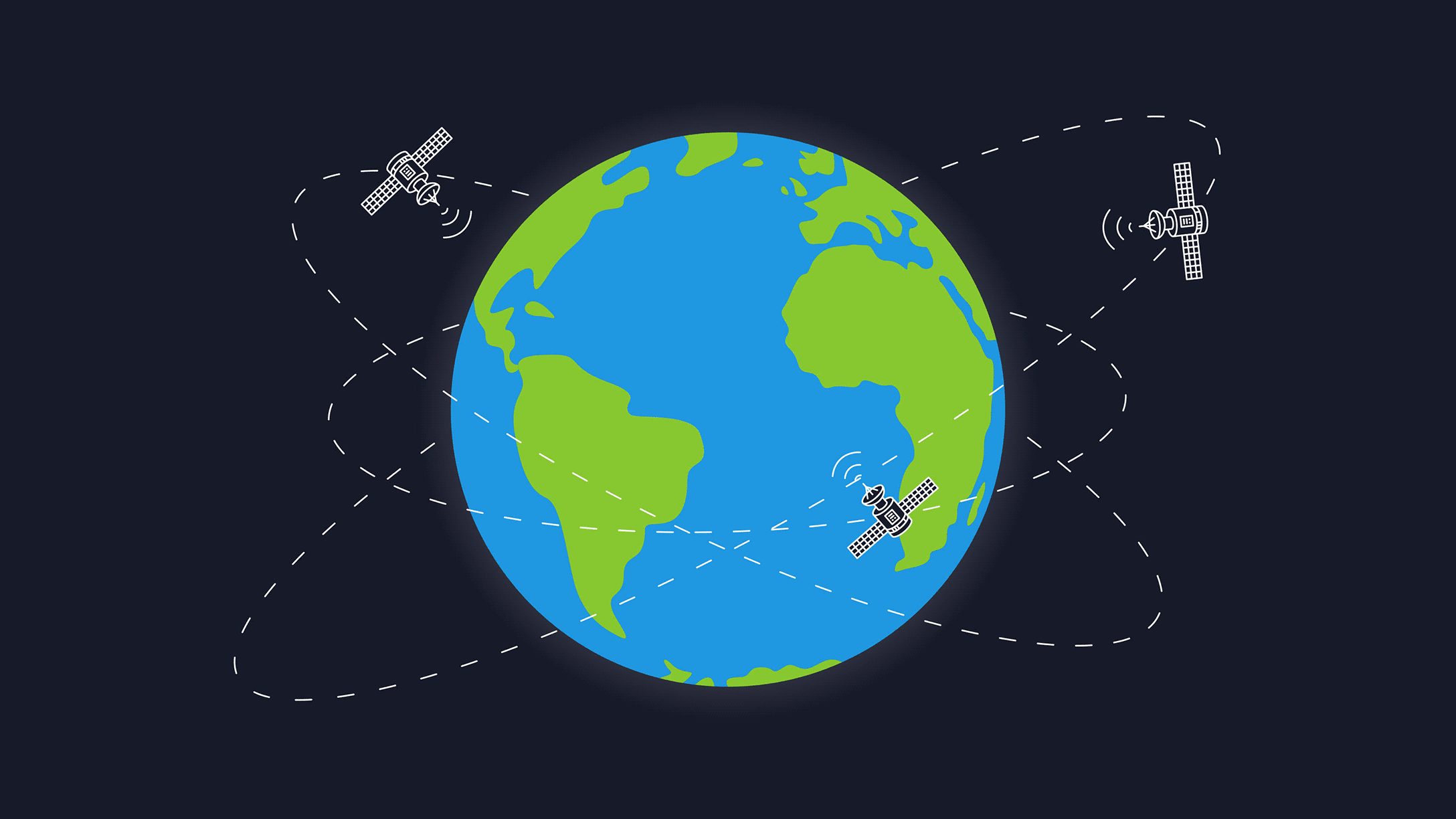
Instead of stars, we use satellites. Over 30 navigation satellites are zipping around high above Earth. These satellites can tell us exactly where we are.
What is GPS?
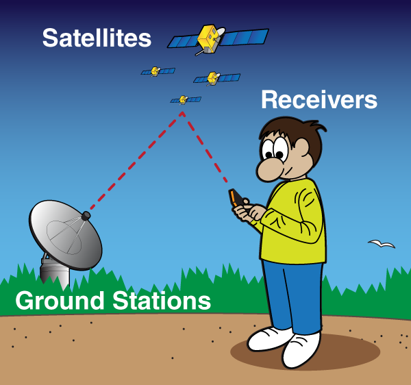
The Global Positioning System (GPS) is made up of satellites, ground stations, and receivers.
GPS is a system. It’s made up of three parts: satellites, ground stations, and receivers.
Satellites act like the stars in constellations—we know where they are supposed to be at any given time.
The ground stations use radar to make sure they are actually where we think they are.
A receiver, like you might find in your phone or in your parents car, is constantly listening for a signal from these satellites. The receiver figures out how far away they are from some of them.
Once the receiver calculates its distance from four or more satellites, it knows exactly where you are. Presto! From miles up in space your location on the ground can be determined with incredible precision! They can usually determine where you are within a few yards of your actual location. More high-tech receivers, though, can figure out where you are to within a few inches!
The ancient sailors of history would be flabbergasted by the speed and ease of pinpointing your location today.
GPS in everyday life

There’s a whole lot of important things GPS is used for—but perhaps nothing is more important than finding the quickest slice of pizza!
Source: NASA website : here
2. NEO-6M GPS module:
The NEO-6M GPS module is shown in the figure below. It comes with an external antenna, and does’t come with header pins. So, you’ll need to get and solder some.

- This module has an external antenna and built-in EEPROM.
- Interface: RS232 TTL
- Power supply: 3V to 5V
- Default baudrate: 9600 bps
- Works with standard NMEA sentences2
The NEO-6M GPS module has four pins: VCC, RX, TX, and GND. The module communicates with the Arduino via serial communication using the TX and RX pins, so the wiring couldn’t be simpler:
| NEO-6M GPS Module | Wiring to Arduino UNO |
| VCC | 5V |
| RX | Not used in this guide |
| TX | PA10 of STM32F4 |
| GND | GND |
Understanding NMEA Sentences
NMEA sentences start with the $ character, and each data field is separated by a comma.
$GPGGA,110617.00,41XX.XXXXX,N,00831.54761,W,1,05,2.68,129.0,M,50.1,M,,*42
$GPGSA,A,3,06,09,30,07,23,,,,,,,,4.43,2.68,3.53*02
$GPGSV,3,1,11,02,48,298,24,03,05,101,24,05,17,292,20,06,71,227,30*7C
$GPGSV,3,2,11,07,47,138,33,09,64,044,28,17,01,199,,19,13,214,*7C
$GPGSV,3,3,11,23,29,054,29,29,01,335,,30,29,167,33*4E
$GPGLL,41XX.XXXXX,N,00831.54761,W,110617.00,A,A*70
$GPRMC,110618.00,A,41XX.XXXXX,N,00831.54753,W,0.078,,030118,,,A*6A
$GPVTG,,T,,M,0.043,N,0.080,K,A*2C
There are different types of NMEA sentences. The type of message is indicated by the characters before the first comma.
The GP after the $ indicates it is a GPS position. The $GPGGA is the basic GPS NMEA message, that provides 3D location and accuracy data. In the following sentence:
$GPGGA,110617.00,41XX.XXXXX,N,00831.54761,W,1,05,2.68,129.0,M,50.1,M,,*42
- 110617 – represents the time at which the fix location was taken, 11:06:17 UTC
- 41XX.XXXXX,N – latitude 41 deg XX.XXXXX’ N
- 00831.54761,W – Longitude 008 deg 31.54761′ W
- 1 – fix quality (0 = invalid; 1= GPS fix; 2 = DGPS fix; 3 = PPS fix; 4 = Real Time Kinematic; 5 = Float RTK; 6 = estimated (dead reckoning); 7 = Manual input mode; 8 = Simulation mode)
- 05 – number of satellites being tracked
- 2.68 – Horizontal dilution of position
- 129.0, M – Altitude, in meters above the sea level
- 50.1, M – Height of geoid (mean sea level) above WGS84 ellipsoid
- empty field – time in seconds since last DGPS update
- empty field – DGPS station ID number
- *42 – the checksum data, always begins with *
The other NMEA sentences provide additional information:
- $GPGSA – GPS DOP and active satellites
- $GPGSV – Detailed GPS satellite information
- $GPGLL – Geographic Latitude and Longitude
- $GPRMC – Essential GPS pvt (position, velocity, time) data
- $GPVTG – Velocity made good
To know what each data field means in each of these sentences, you can consult NMEA data here.
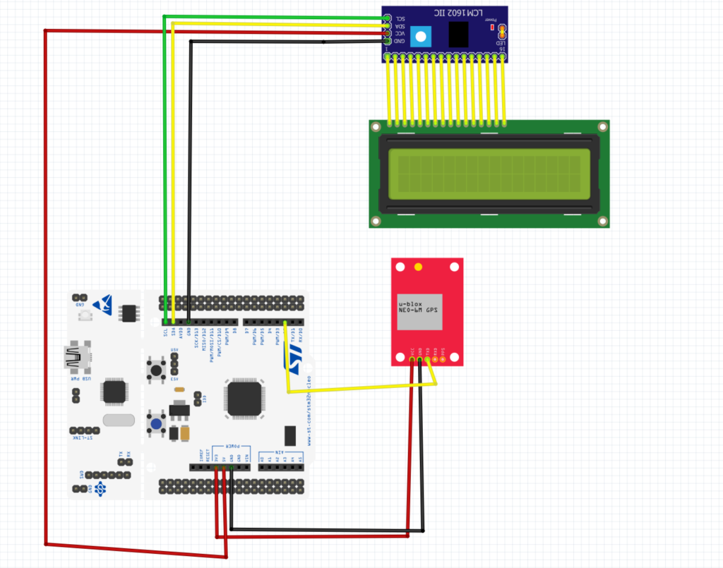
3. Connection with STM32F4
In this guide, we need the following
- STM32F411RE Nucelo-64
- LCD2004 I2C
- NEO-6M GPS module
The connection should be as following:
4. Code:
We start of by initializing UART1 in interrupt mode for the receiver as following:
void uart_gps_init()
	{
	#define AF07 0x07
	RCC->APB2ENR|=RCC_APB2ENR_USART1EN;
	RCC->AHB1ENR|=RCC_AHB1ENR_GPIOAEN;

	GPIOA->MODER|=GPIO_MODER_MODE10_1;
	GPIOA->MODER&=~GPIO_MODER_MODE10_0;

	GPIOA->MODER|=GPIO_MODER_MODE9_1;
	GPIOA->MODER&=~GPIO_MODER_MODE9_0;

	GPIOA->AFR[1]|=(AF07<<4)|(AF07<<8); //ALT7 for UART2 (PA2 and PA3)
	USART1->BRR  = 0x0681;    //9600 @16MHz
	USART1->CR1 |= (1<<2)|(1<<3)|(1<<5)|(1<<13);
	NVIC_EnableIRQ(USART1_IRQn);

	}
then we declare some required variables as following:
volatile unsigned char Gpsdata;             // for incoming serial data
unsigned int finish =0;            // indicate end of message
unsigned int pos_cnt=0;            // position counter
unsigned int lat_cnt=0;            // latitude data counter
unsigned int log_cnt=0;            // longitude data counter
unsigned int flg    =0;            // GPS flag
unsigned int com_cnt=0;            // comma counter
unsigned char lat[20];             // latitude array
unsigned char lg[20];              // longitude array
int i=0;
unsigned char dir,dir1;
Within the interrupt handler, we shall construct the location as following:
void USART1_IRQHandler(void){

if(USART1->SR&USART_SR_RXNE) //check if the read data register is not empty
{
Gpsdata=USART1->DR;
ITM_SendChar(Gpsdata);
flg = 1;

if(finish == 0){
if( Gpsdata=='$' && pos_cnt == 0)  // finding GPRMC header
         pos_cnt=1;
       if( Gpsdata=='G' && pos_cnt == 1)
         pos_cnt=2;
       if( Gpsdata=='P' && pos_cnt == 2)
         pos_cnt=3;
       if( Gpsdata=='R' && pos_cnt == 3)
         pos_cnt=4;
       if( Gpsdata=='M' && pos_cnt == 4)
         pos_cnt=5;
       if(Gpsdata=='C'  &&  pos_cnt == 5 )
				 //data[i]=Gpsdata;i++;
         pos_cnt=6;
       if(pos_cnt==6    &&  Gpsdata ==','){  // count commas in message
         com_cnt++;
         flg=0;
       }
				if(Gpsdata=='N'||Gpsdata=='S'){dir=Gpsdata;}
				if(Gpsdata=='E'||Gpsdata=='W'){dir1=Gpsdata;}
       if(com_cnt==3 && flg==1){
        lat[lat_cnt++] =  Gpsdata;        // latitude
        flg=0;
       }

       if(com_cnt==5 && flg==1){
         lg[log_cnt++] =  Gpsdata;        // longitude
         flg=0;
       }

       if( Gpsdata == '*' && com_cnt >= 5 && flg == 1){

				 lat[lat_cnt]=dir;
				 lat[lat_cnt+1] ='\0';				 // end of GPRMC message
				 lg[log_cnt]  =dir1;
         lg[log_cnt+1]  ='\0';
         lat_cnt = 0;
         log_cnt = 0;
         flg     = 0;
         finish  = 1;
         com_cnt = 0;
					i=0;
      }
     }
}
}
for the lcd part, you can download the code from here.
Hence, the entire code is as following:
#include "LiquidCrystal_PCF8574.h"
volatile unsigned char Gpsdata; // for incoming serial data
unsigned int finish =0; // indicate end of message
unsigned int pos_cnt=0; // position counter
unsigned int lat_cnt=0; // latitude data counter
unsigned int log_cnt=0; // longitude data counter
unsigned int flg =0; // GPS flag
unsigned int com_cnt=0; // comma counter
unsigned char lat[20]; // latitude array
unsigned char lg[20]; // longitude array
int i=0;
unsigned char dir,dir1;
void uart_gps_init()
{
#define AF07 0x07
RCC->APB2ENR|=RCC_APB2ENR_USART1EN;
RCC->AHB1ENR|=RCC_AHB1ENR_GPIOAEN;
GPIOA->MODER|=GPIO_MODER_MODE10_1;
GPIOA->MODER&=~GPIO_MODER_MODE10_0;
GPIOA->MODER|=GPIO_MODER_MODE9_1;
GPIOA->MODER&=~GPIO_MODER_MODE9_0;
GPIOA->AFR[1]|=(AF07<<4)|(AF07<<8); //ALT7 for UART2 (PA2 and PA3)
USART1->BRR = 0x0681; //9600 @16MHz
USART1->CR1 |= (1<<2)|(1<<3)|(1<<5)|(1<<13);
NVIC_EnableIRQ(USART1_IRQn);
}
int main(void)
{
__disable_irq();
uart_gps_init();
__enable_irq();
lcd_init();
setCursor(0,0);
lcd_send_string("GPS NEO with STM32");
setCursor(0,1);
lcd_send_string("EmbeddedExpertIO");
for(volatile int i=0;i<3000000;i++);
lcd_clear();
while(1)
{
{
setCursor(0,0);
lcd_send_string("Latitude: ");
setCursor(0,1);
lcd_send_string((char *)lat);
setCursor(0,2);
lcd_send_string("Longitude: ");
setCursor(0,3);
lcd_send_string((char *)lg);
}
}
}
void USART1_IRQHandler(void){
if(USART1->SR&USART_SR_RXNE) //check if the read data register is not empty
{
Gpsdata=USART1->DR;
flg = 1;
if(finish == 0){
if( Gpsdata=='$' && pos_cnt == 0) // finding GPRMC header
pos_cnt=1;
if( Gpsdata=='G' && pos_cnt == 1)
pos_cnt=2;
if( Gpsdata=='P' && pos_cnt == 2)
pos_cnt=3;
if( Gpsdata=='R' && pos_cnt == 3)
pos_cnt=4;
if( Gpsdata=='M' && pos_cnt == 4)
pos_cnt=5;
if(Gpsdata=='C' && pos_cnt == 5 )
//data[i]=Gpsdata;i++;
pos_cnt=6;
if(pos_cnt==6 && Gpsdata ==','){ // count commas in message
com_cnt++;
flg=0;
}
if(Gpsdata=='N'||Gpsdata=='S'){dir=Gpsdata;}
if(Gpsdata=='E'||Gpsdata=='W'){dir1=Gpsdata;}
if(com_cnt==3 && flg==1){
lat[lat_cnt++] = Gpsdata; // latitude
flg=0;
}
if(com_cnt==5 && flg==1){
lg[log_cnt++] = Gpsdata; // longitude
flg=0;
}
if( Gpsdata == '*' && com_cnt >= 5 && flg == 1){
lat[lat_cnt]=dir;
lat[lat_cnt+1] ='\0'; // end of GPRMC message
lg[log_cnt] =dir1;
lg[log_cnt+1] ='\0';
lat_cnt = 0;
log_cnt = 0;
flg = 0;
finish = 1;
com_cnt = 0;
i=0;
}
}
}
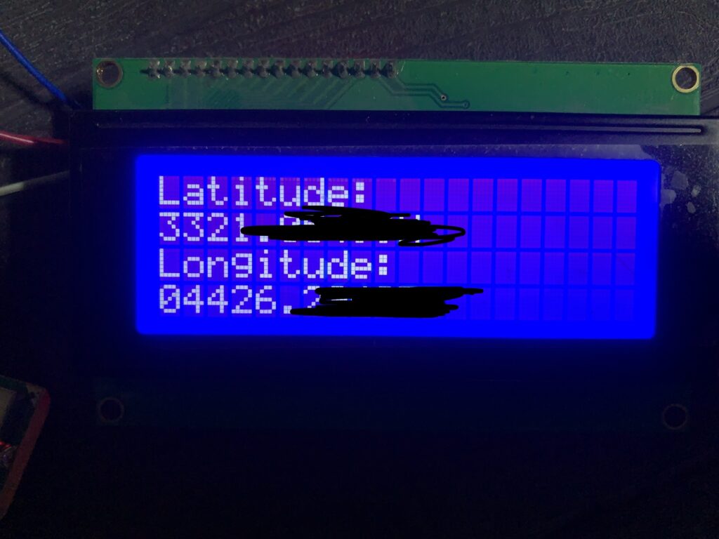
}5. Result:
When you run the code, you should get something like this
Note: you need to be outside of the home for the GPS to work properly since this module designed for automotive industry
Happy coding 🙂
Add Comment