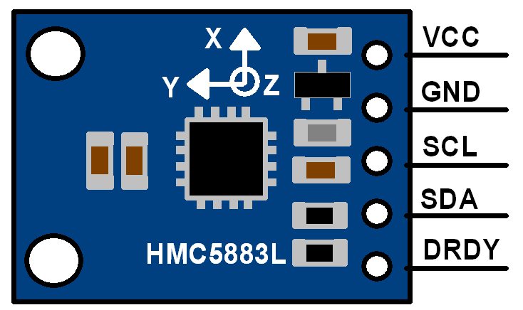
In this weekly guide, we shall take a look at the HMC5883L magnetic field sensor and measure the magnetic field in the three axis (x, y and z).
In this guide, we shall cover the following:
- What is magnetometer
- Interfacing HMC5883L with STM32F4
- Code
- Demo
1.1 What is magnetometer:
magnetometer,, instrument for measuring the strength and sometimes the direction of magnetic fields, including those on or near the Earth and in space. Magnetometers are also used to calibrateelectromagnets and permanent magnets and to determine the magnetization of materials(source).
1.2 HMC5883L:
The Honeywell HMC5883L is a surface-mount, multi-chip module designed for low-field magnetic sensing with a digital interface for applications such as low-cost compassing and magnetometry. The HMC5883L includes our state-of-the-art, high-resolution HMC118X series magneto-resistive sensors plus an ASIC containing amplification, automatic degaussing strap drivers, offset cancellation, and a 12-bit ADC that enables 1° to 2° compass heading accuracy. The I2C serial bus allows for easy interface. The HMC5883L is a 3.0×3.0x0.9mm surface mount 16-pin leadless chip carrier (LCC). Applications for the HMC5883L include Mobile Phones, Netbooks, Consumer Electronics, Auto Navigation Systems, and Personal Navigation Devices.


2. Interfacing HMC5883L with STM32:
Since the module uses I2C bus to communicate with STM32, we shall use the i2c Read/Wire multiple bytes for earlier post(here) and we shall use Liquid Crystal Display (LCD) in I2C mode (here).
Before we start, we need take a look at the register from the datasheet
Here is the list of the registers:

Hence we can start by defining the registers in the source file (HMC5883L.c)
#define mode_register (0x02)
#define config_b      (0x01)
and the address of the chip (from i2c scanner post (here))
#define address (0x1E)
Now, in configuration register b, we need to configure the scale as shown:


Hence we can use enum for that in the header file (HMC5883L.h)
typedef enum
	{
	HMC5883L_RANGE_0_88GA	=0x00,
	HMC5883L_RANGE_1_3GA	=0x20,
	HMC5883L_RANGE_1_9GA	=0x40,
	HMC5883L_RANGE_2_5GA    =0x60,
	HMC5883L_RANGE_4GA      =0x80,
	HMC5883L_RANGE_4_7GA    =0xA0,
	HMC5883L_RANGE_5_7GA    =0xC0,
	HMC5883L_RANGE_8_1GA    =0xE0

	}HMC5883LScale_t;
Hence the initializing function:
int8_t HMC5883L_Init(HMC5883LScale_t scale)
	{
	int8_t state;
	i2c_writeByte(address, mode_register, 0x00);

	if(state==-1){return -1;}

	i2c_writeByte(address, 0x00, 0xD0);

	if(state==-1){return -1;}

	switch(scale)
	    {
		case HMC5883L_RANGE_0_88GA:
			m_Scale = 0.073f;
		    break;

		case HMC5883L_RANGE_1_3GA:
			m_Scale = 0.92f;
		    break;

		case HMC5883L_RANGE_1_9GA:
			m_Scale = 1.2f;
		    break;

		case HMC5883L_RANGE_2_5GA:
			m_Scale = 1.52f;
		    break;

		case HMC5883L_RANGE_4GA:
			m_Scale = 2.27f;
		    break;

		case HMC5883L_RANGE_4_7GA:
			m_Scale = 2.56f;
		    break;

		case HMC5883L_RANGE_5_7GA:
			m_Scale = 3.03f;
		    break;

		case HMC5883L_RANGE_8_1GA:
			m_Scale = 4.35f;
		    break;

		default:
		    break;
	    }

	state = i2c_writeByte(address, config_b, scale);
	if(state==-1){return -1;}
	return 0;
	}
For reading the value, we can use read_multibyte function starting from address 0x03 as following:
int8_t update_HMC5883L(void)
	{

	int8_t state;
	state=i2c_ReadMulti(address, 0x03, 6, (char *)gaus_data);
	if(state==-1){return -1;}
	return 0;
	}
For getting the scaled value, we can use simple 3 functions for this purpose:
float getGausX(void)
	{
	uint16_t data=gaus_data[0]<<8|gaus_data[1];
	float g=data*m_Scale;
	return g;
	}

float getGausY(void)
	{
	uint16_t data=gaus_data[4]<<8|gaus_data[5];
	float g=data*m_Scale;
	return g;
	}

float getGausZ(void)
	{
	uint16_t data=gaus_data[2]<<8|gaus_data[3];
	float g=data*m_Scale;
	return g;
	}
In the main function
We can include the lLCD with I2C, the HMC5883L and enable FPU (floating point uint) as following
#include "LiquidCrystal_PCF8574.h"
#include "delay.h"
#include "stdio.h"
#include "HMC5883L.h"
#include "stm32f4xx.h"
float gx,gy,gz;


/*
 * This function shall enable the FPU unit in cortex-M4/M7 based MCU
 * Note: Not all Cortex-M4/M7 has embedded FPU
 *
 * */
void enable_fpu()
	{
	SCB->CPACR |= ((3UL << 10*2)|(3UL << 11*2));

	}


int main(void)
	{
	enable_fpu();
	systick_init_ms(16000000);
	lcd_init();
	HMC5883L_Init(HMC5883L_RANGE_2_5GA);
	setCursor(0,0);
	lcd_send_string("magnetometer");


	while(1)
		{
		update_HMC5883L();
		gx=getGausX();
		gy=getGausY();
		gz=getGausZ();
		char data[20];
		sprintf(data,"Gx=%0.5f       ",gx);
		setCursor(0, 1); lcd_send_string(data);

		sprintf(data,"Gy=%0.5f       ",gy);
		setCursor(0, 2); lcd_send_string(data);

		sprintf(data,"Gz=%0.5f     ",gz);
		setCursor(0, 3); lcd_send_string(data);
		delay(100);


		}


	}
in the while 1 loop
- Update the HMC5883L
- Get the scaled data
- Display the data on the display
3. Code:
You may download the source code from here:
4. Demo:
Happy coding 🙂
Add Comment